Heavy Equipment Gear Deburring
Case A
JOB NO. 335
CUSTOM HEAVY GEAR DEBURRING
APPLICATION
A manufacturer of heavy equipment power train components required a chamfer to be put on both sides of a helical gear. For this application, there could be absolutely no residual material left over by the grinder cut. These gears were moderately heavy, requiring a robust shuttle system to move the gear from work to load position. This machine was to be hand loaded, requiring specific safety implements. The customer also had paint and floor spacing specifications including a custom free-standing electrical cabinet.
SOLUTION
Processing
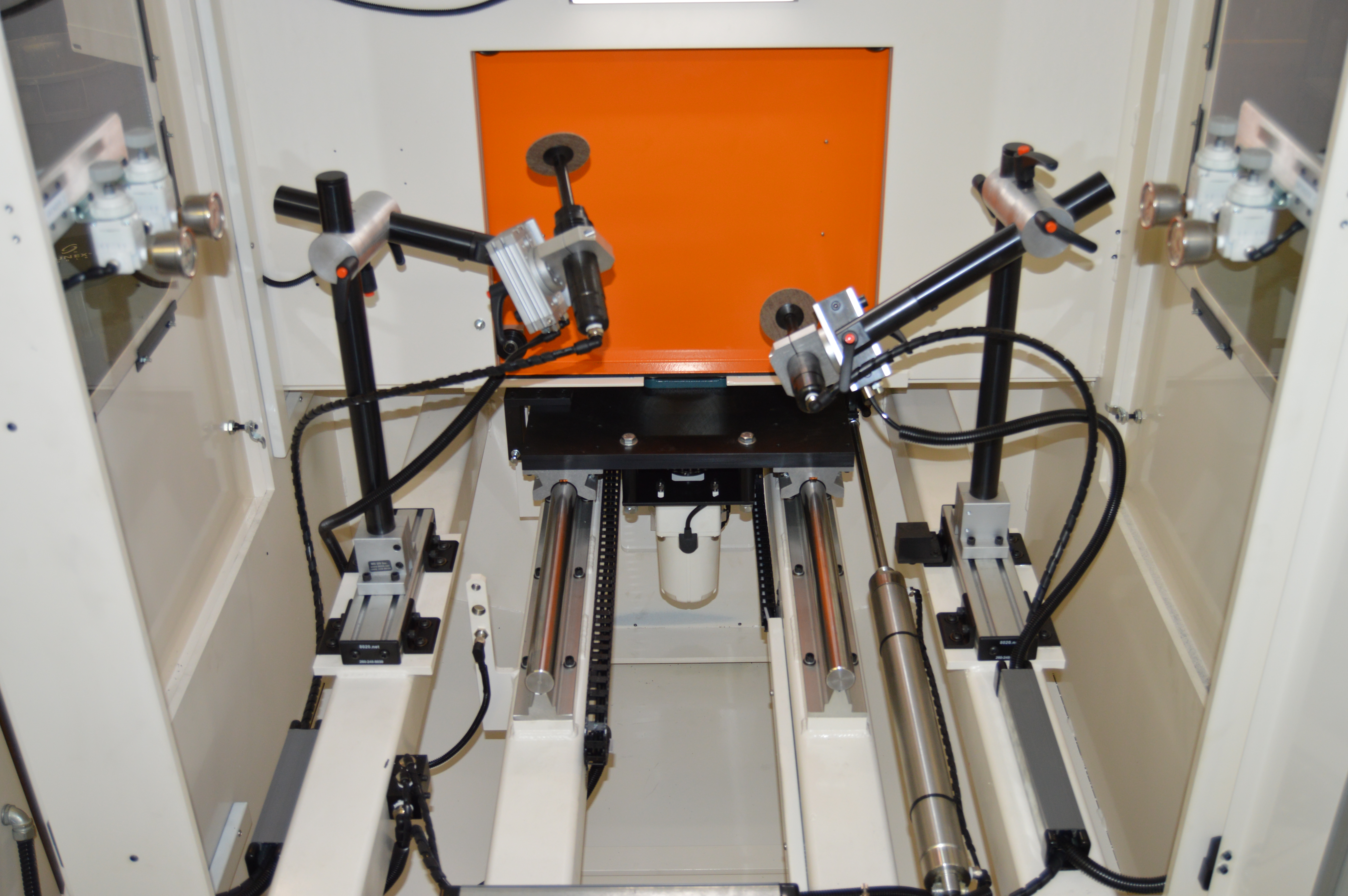
- When chamfering a helical gear with a grinding wheel, the cutter should enter the acute side of a tooth and exit the obtuse side. To achieve this, the work piece is moved clockwise for a cut, then counter-clockwise for the opposite side.
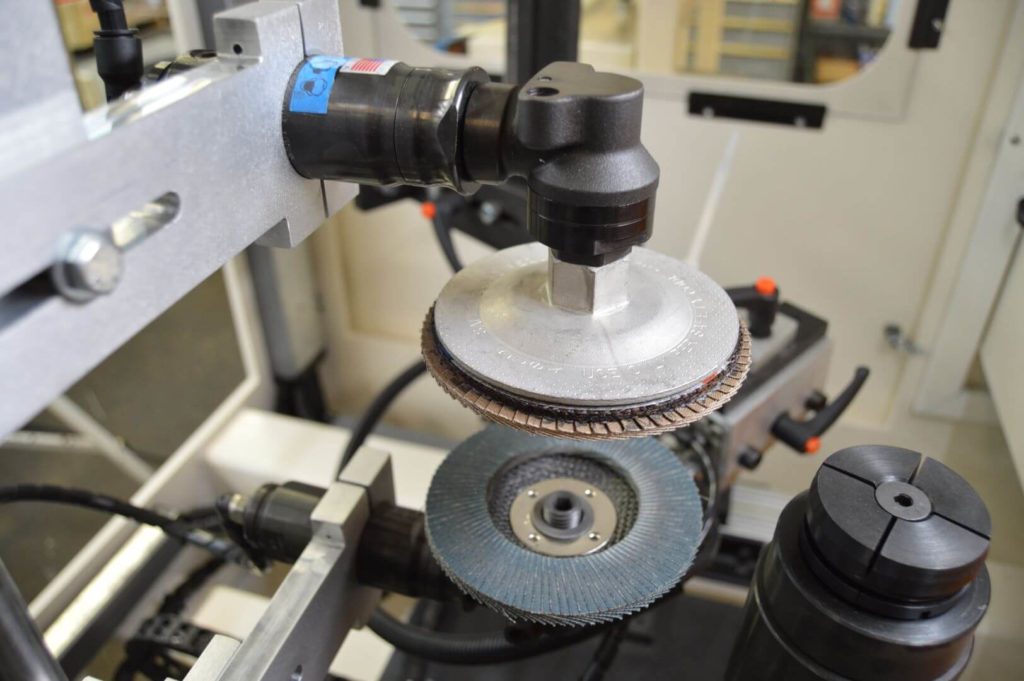
- The chamfer is done by a set of 3’-4” grinding wheels driven by 20,000rpm air motors. The air motors are held near center by a rotary actuator. This allows them to follow the work surface contours while cutting. Precision regulators are used to control cut and lift pressures. Once the optimal pressure settings have been determined via trial and error, these settings can be saved to maintain cycle to cycle performance.
- Grinding heads are held by a pair of adjustable grinder arms. CDMC offers many variations of this assembly.
- In order to remove the residual material left by chamfering, a set of abrasive flap wheels driven by a lower rpm air motor are used parallel to the gear face. The sanding heads are horizontally and vertically adjustable.
- Sanding heads are brought to and from work position by a pair of pneumatic linear slides. Cut and lift pressures are precision regulated.
- A ¾”-1” steel plate is used to carry the drive spindle assembly from work to load positions. This plate is carried by a set of 1.5”-2” linear rails. A 1.5” air cylinder is used to actuate this motion.
- Part spindle rotation is chain driven by an offset motor. Offsetting the drive assembly enables us to provide a more easily serviceable drive assembly. Chain driving prevents any backlash that could be experienced with a belt drive.
Safety/On Site Requirements
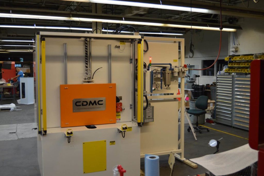
- This machine has paint spec’s for electrical and pneumatic components. CDMC is willing to fulfill paint spec’s for a cost.
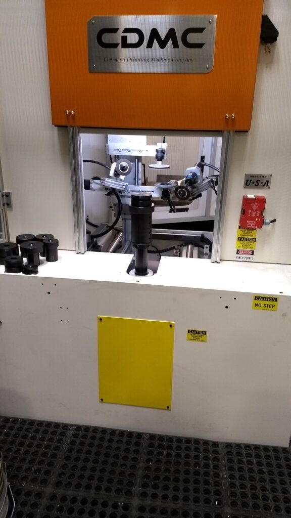
- Electronic locking systems are mounted to manual doors for the highest level of safety. These switches disallow manual doors from being opened during operation and if bypassed, will send the machine into a fault state.
- Machine base is adapted for duct work and a custom pedestal stands near the unit, per customer request. Dust collection unit is from an outside manufacturer.
- Cabinets are mounted to a custom frame assembly in an attempt to condense the machine cell’s footprint.
- A custom front enclosure protects the operator during machine cycle. The enclosure is equipped with a set of light curtains and a “2 hand start” system. Both start buttons must be pressed for a cycle to begin and if the light curtain is breached, the machine will immediately stop and enter a fault state.