Dual Sided Deburring
Case A & B
JOBS NO. 132 & 281
DUAL SIDE FLAT COMPONENT DEBURRING
Application
A manufacturer of various automotive clutch components needed a solution to deburr large production quantities of flat metal rings. These machines needed to process many parts in a short period of time while taking up as little shop space as possible. The ability to treat a masked ID on some parts was also required along with dust collection for the dry process.
Solution
Machine Bases
- A long and tall base made of ½” steel plate is used for the mane machine. Its height and length allow four brush heads to be used and vertically adjusted. The back wall must be robust enough to support a heavy brush head/linear rail assemblies.
- A smaller base is provided to house the optional secondary operation.
Processing (main machine)
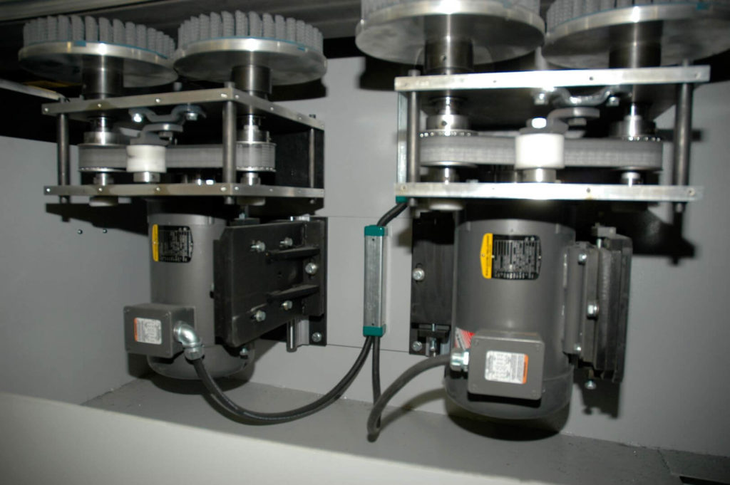
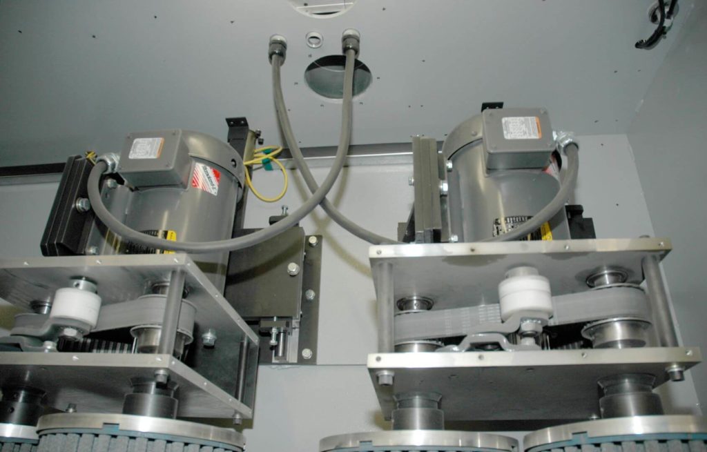
- Parts arrive at incoming conveyor, enter the work area and are secured via BUNTING MAGNETICS conveyor. With top sides exposed, parts are passed beneath a pair of dual-drive brush assemblies consisting of two 8”-12” nylon abrasive end brushes being belt driven by a single, offset large frame electric motor.
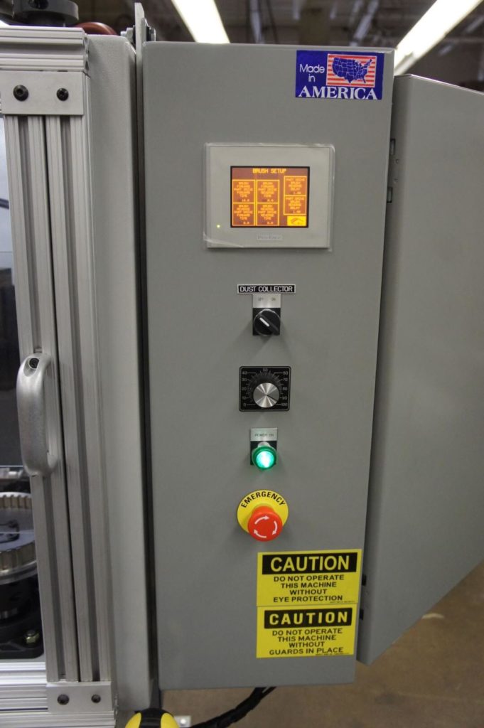
- Amperage feedback from these motors is used within the PLC program to set brush depths/cutting pressures via the machine’s HMI (Auto Amp Compensation). Brush heads are fed/retracted along linear rail assemblies via intelligent linear actuator assemblies. Optimizing AAC settings allows the machine to create consistent results from cycle to cycle. Dual-drive brush heads are used to save floor space and negate the need for independent motors for each brush.
- Once parts have passed through the first pair of brush heads, they are transferred to an overhead conveyor that will allow the previously masked (bottom) side to be deburred in the same manner as the top side, but with AAC adjustments being performed by linear actuator/rails at the conveyor rather than brush heads.
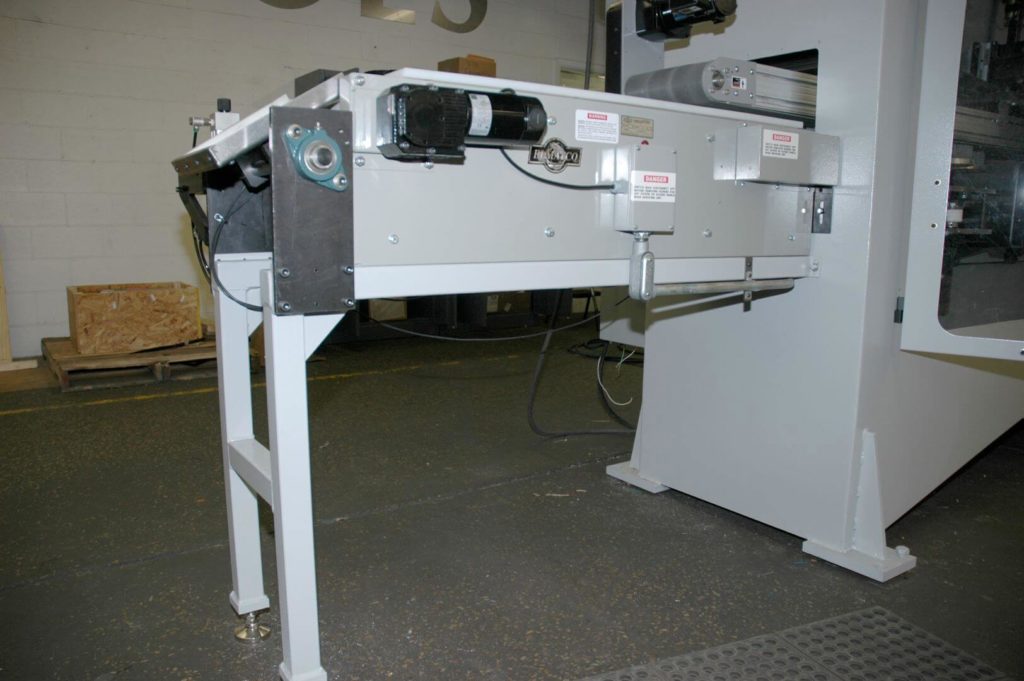
- Parts exit the main machine onto a cleated ELMATCO demagnetizer belt and are stripped of any residual magnetism. They are now either unloaded or transferred onto the auxiliary station.
(auxiliary station)
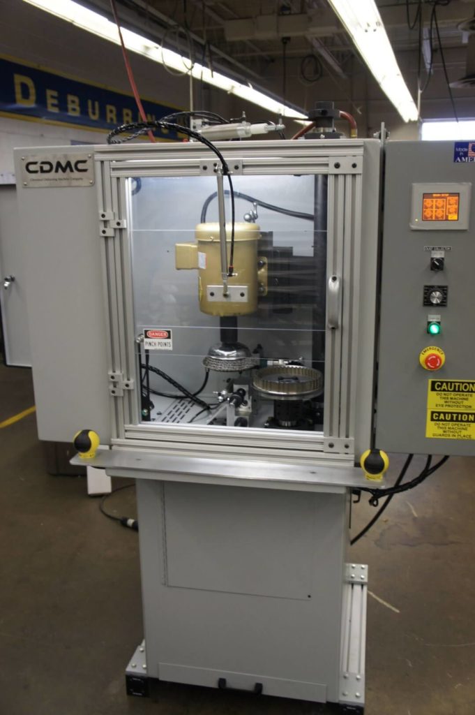
NOTE: This automated station is also available (pictured as “machine B”) in a stand-alone, manually loaded unit. Load operators are protected by a 2-hand start system and a polycarbonate glass vertical auto door.
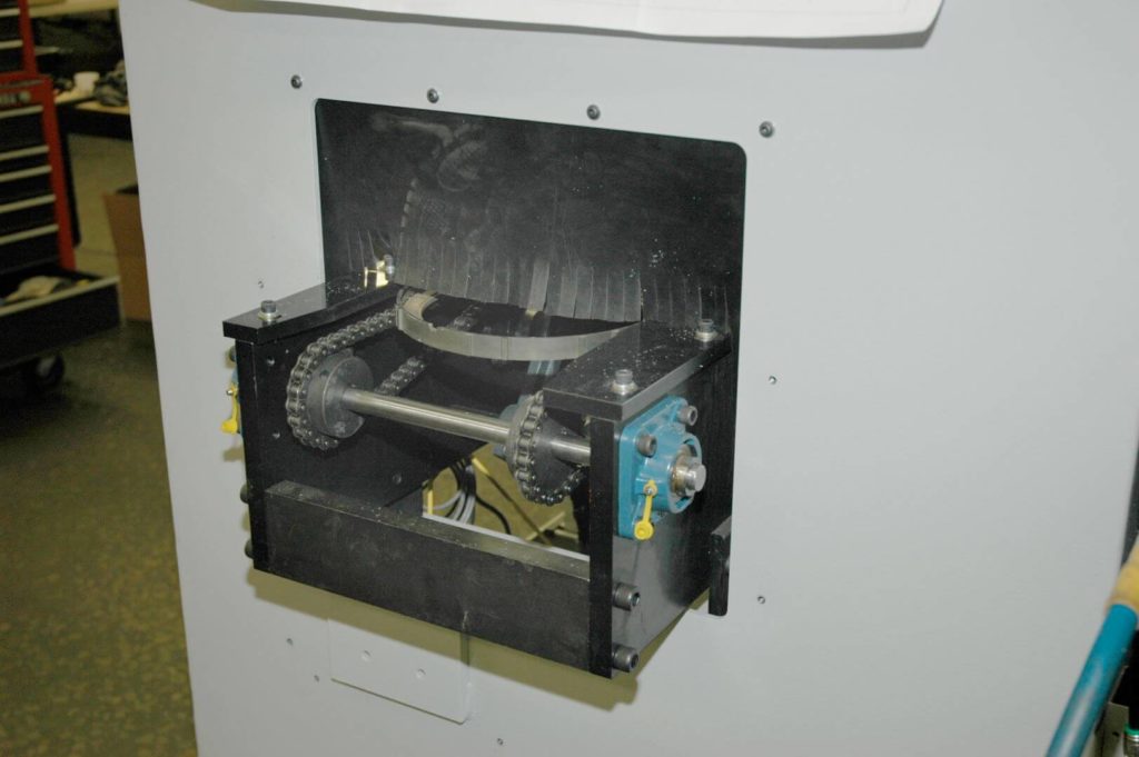
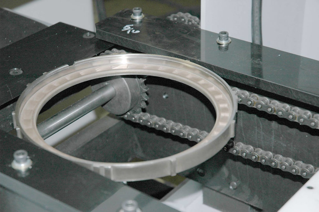
- Parts are carried via dual conveyor belt/chain assembly. This allows them to be carried into the work position at the edge of their OD while allowing clamping and brushing to be done to the parts’ ID’s. The conveyor system is chain-driven by an offset electric motor.
- A set of linear pneumatic escapement cylinders stop/allow feed into the working position. Once parts have arrived at “work”, a mobile spindle assembly rises into place and clamps the part ID pneumatically via collet assembly.
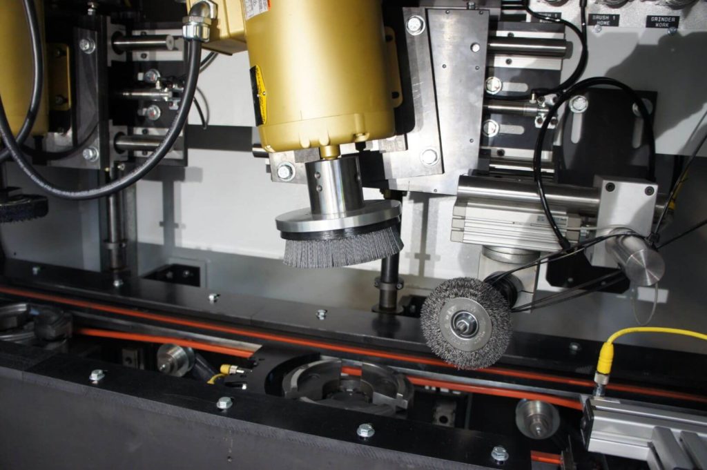
- Clamped at one of two available stations, parts are treated by a 3” steel crimped wire radial brush, 6” nylon abrasive end brush and 6”-8” nylon abrasive radial brush.
- The steel wire brush is directly driven by a high rpm air motor held near center by a pneumatic rotary actuator. Rotary actuation allows the wire brush to follow the contours of the work surface and its cut/lift pressures are adjustable via precision regulators.
- Nylon abrasive brushes are directly driven by large frame electric motors and use AAC to determine aggressiveness of cut.
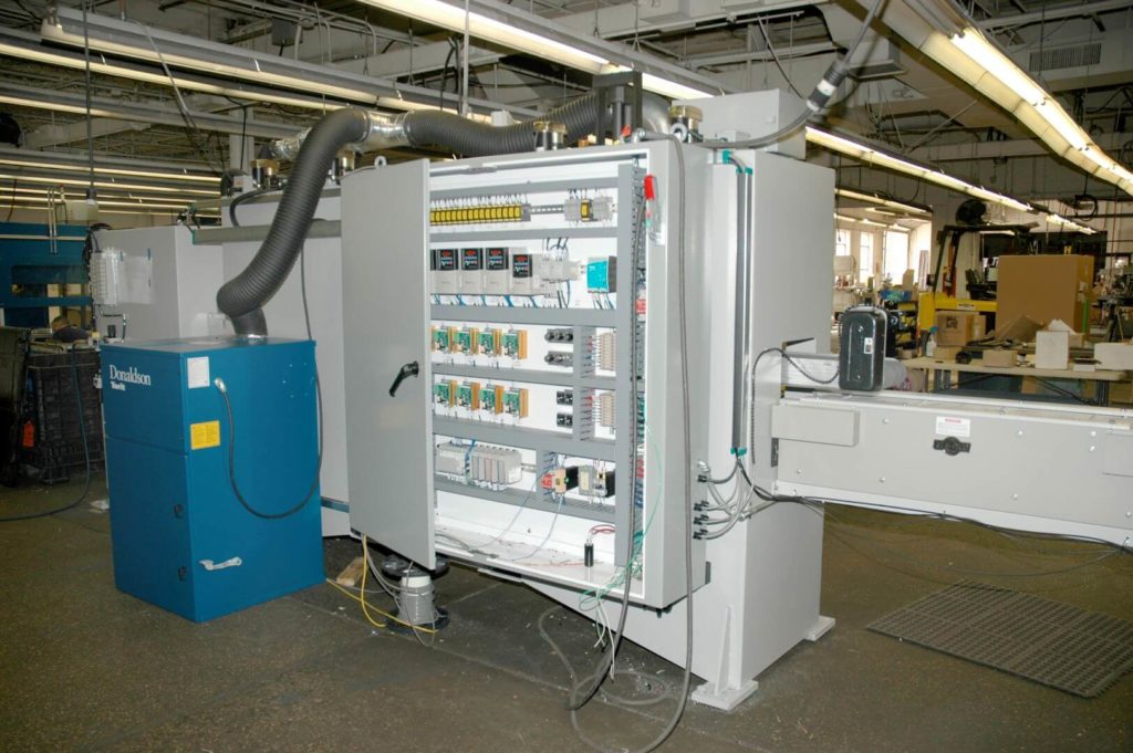
Onsite Requirements
A DONALDSON TORIT stand-alone dust collection unit is provided by CDMC along with all necessary duct work.
Machine A
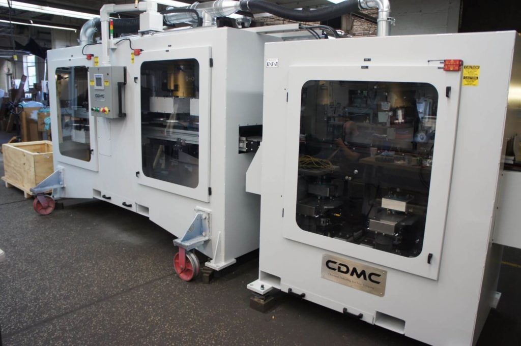
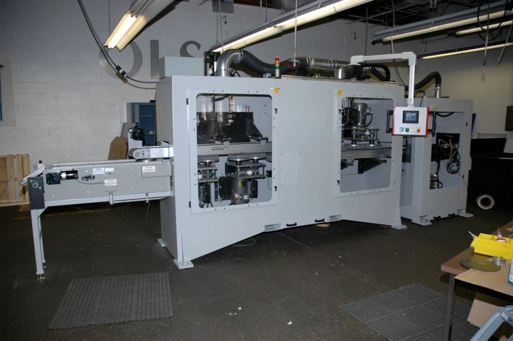
Machine B