Clutch Components
Case C
JOB NO. 262
DUAL LANE CLUTCH COMPONENT DEBURRING
Application
A manufacturer needed a solution for clutch component deburring of OD’s on a family of gears. The customer required a fast cycle time and requested the ability to run two separate part styles during the same cycle. The required work surfaces dictated that we would be unable to process these gears in a standard fashion, so a custom process was required.
Solution
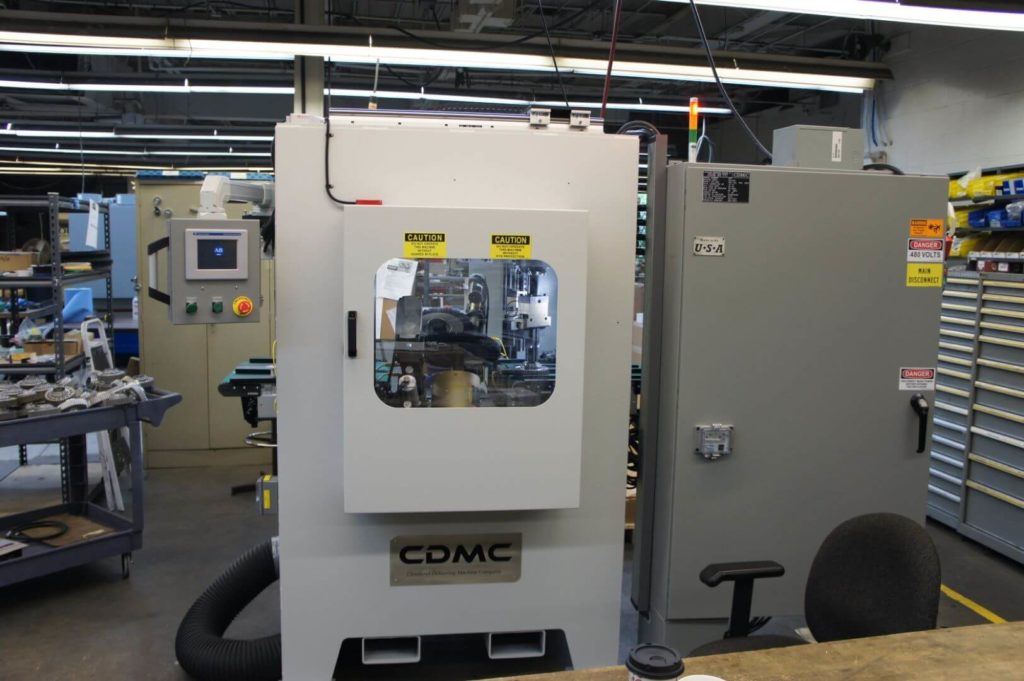
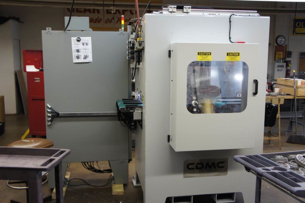
Machine Base
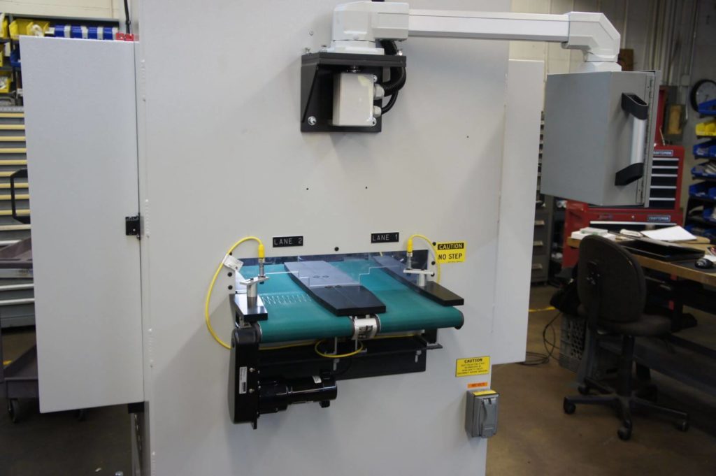
- A low, rectangular base with slotted roof openings allows for clamp spindle assemblies to hang/travel from the roof of the machine.
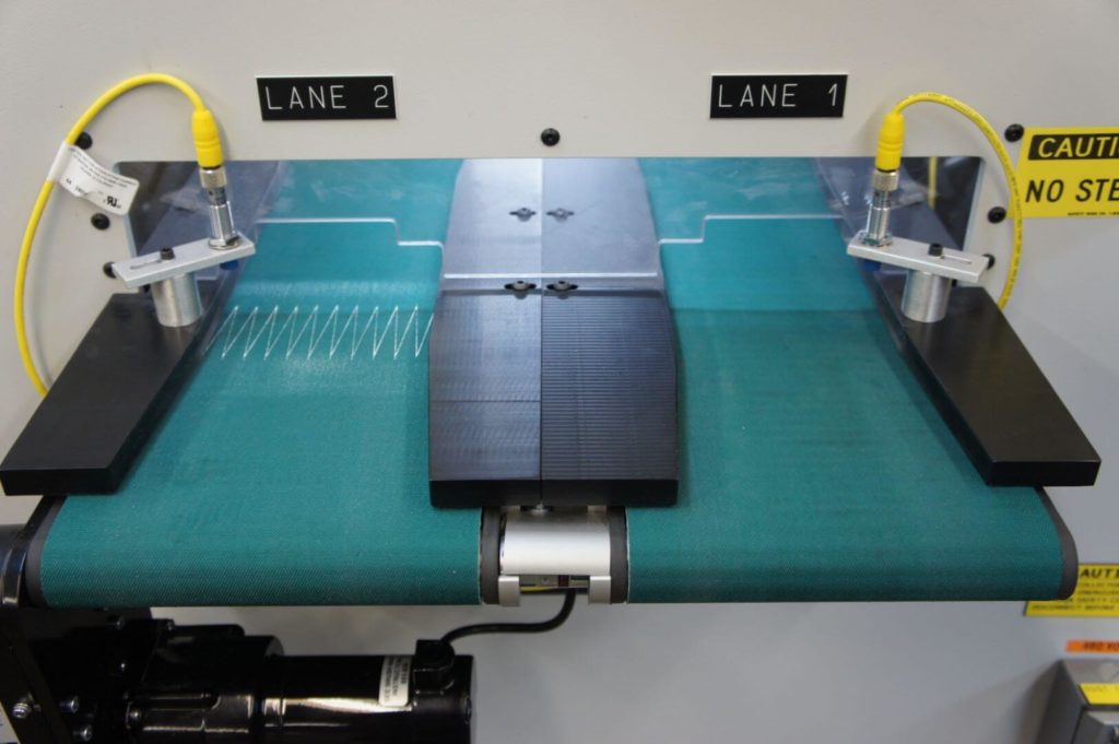
- Load/unload openings are created to allow the use of four conveyors/two work lanes.
- Cupped manual access doors allow for brush head adjustment/movement while keeping machine footprint small.
Processing
- Part types are selected via HMI and parts begin to feed to the machine. Adjustable resin edge pieces are used to guide parts along the dual conveyor assembly to a “pick” position nest located at the end of the incoming conveyors.
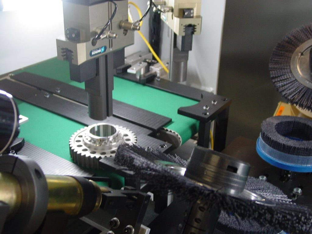
- Custom-tooled work spindles are lowered into place via linear rail assembly and open to clamp the gears’ ID’s. Work spindles consist of a two-jaw SCHUNK gripper coupled to an offset belt-driven spindle assembly. The spindle is driven via D/C motor, so rotational speed is adjustable via HMI screens.
- Once lifted from the incoming conveyors, gears are brought to a central “work” position via robust linear rail/actuator systems located on the machine’s roof. Intelligent linear actuators ensure that “work” position is consistent from cycle to cycle.
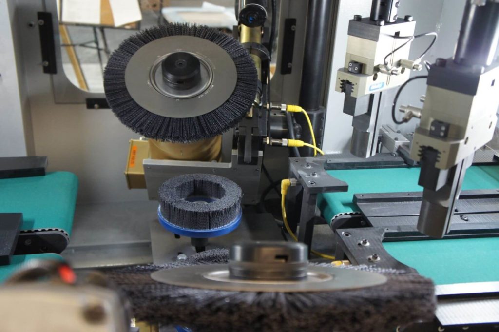
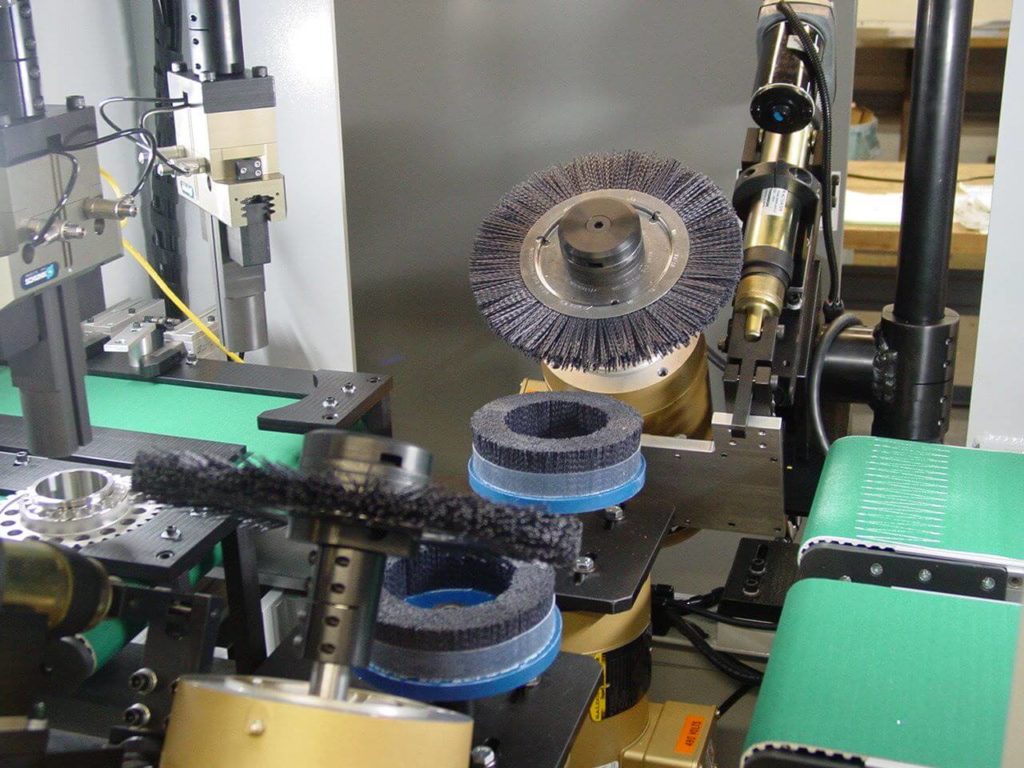
- As gears rotate at the “work” position, they are treated by nylon abrasive/silicon carbide brushes. All brushes are directly driven by large frame D/C motors.
- 10”-14” radial brushes used to treat the upper-most work surface are brought into place by a large pneumatic cylinder, while Auto Amp Compensation adjustments are made via intelligent linear actuators. This assembly is also mounted to a large pivot shaft, allowing adjustments to be made to cut angle.
- 6”-10” end brushes are used to treat the work surface underneath these gears. End brush assemblies are mounted to a linear rail & actuator system, using AAC feedback to determine aggressiveness of cut.
- Once deburred, gears are carried to exit conveyors matching the entry conveyors and dropped off to exit the machine.
- Each work lane operates independently and lanes do not need to be operated in tandem.