Transmission Gear Deburring
JOBS NO. 316 & 305
STANDARDIZED ROBOTIC SHAFT AND GEAR DEBURRING
Application
Numerous manufacturers of automotive gears, like transmission gears or shafts used in steering systems required a universal system for deburring and/or chamfering a wide range of parts. This machine had to have a small footprint and be versatile, capable, easily comprehended, and comply with any/all safety requirements. Some customers have custom paint requirements as well.
Solution
Machine Base
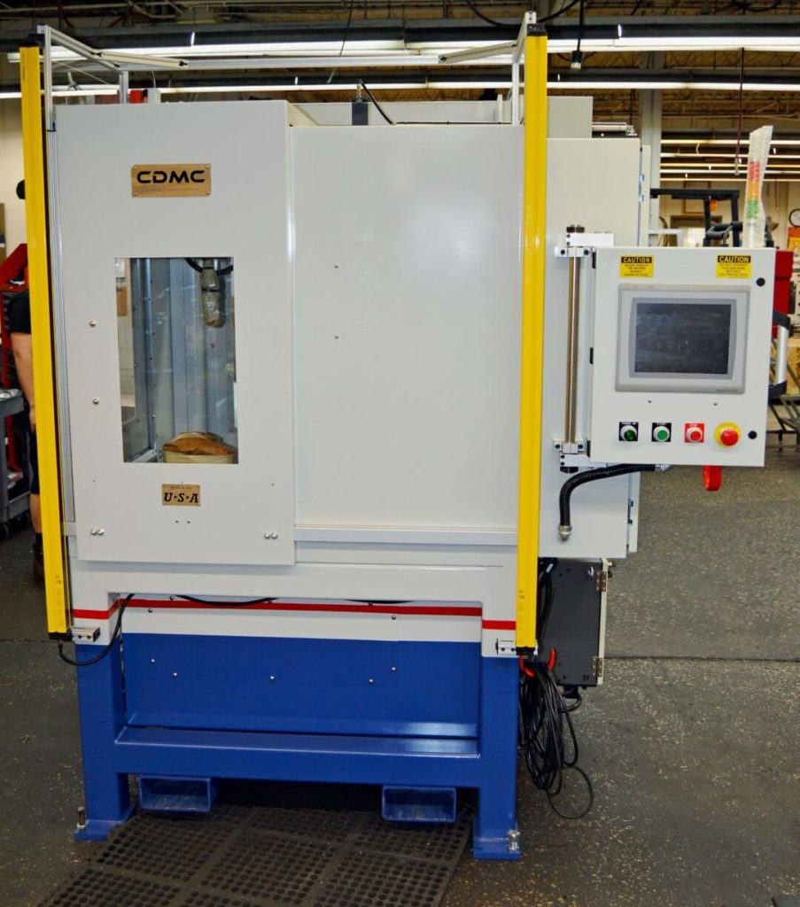
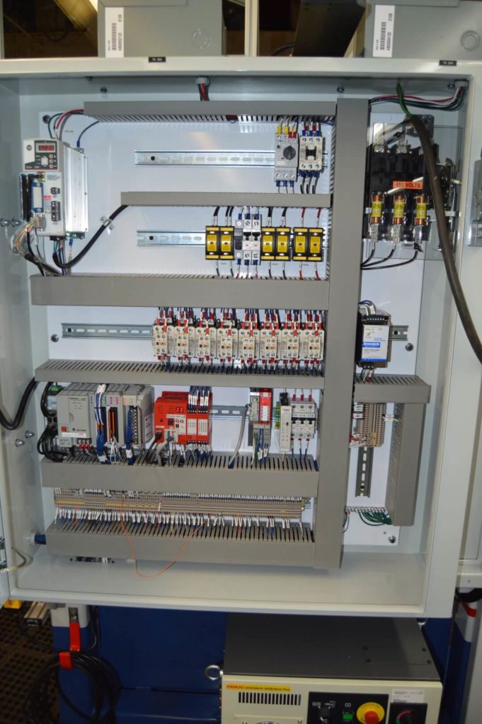
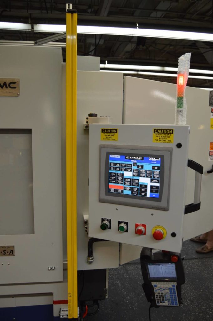
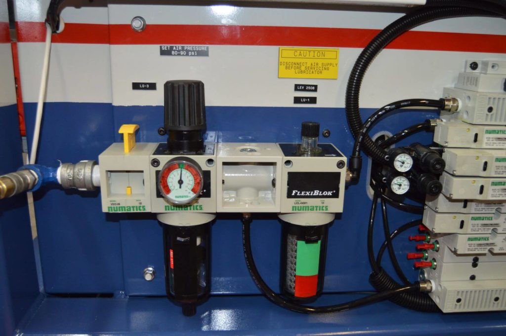
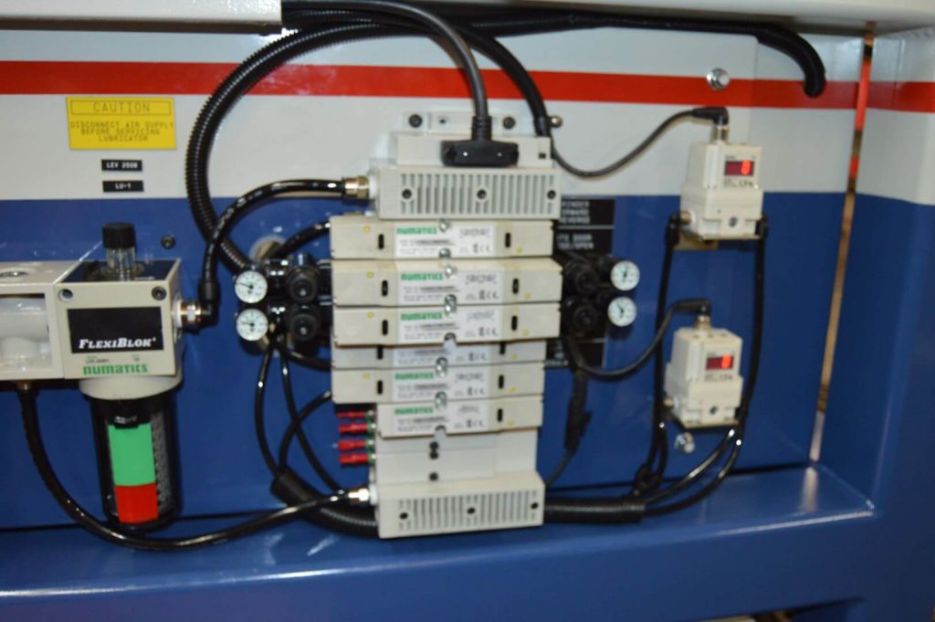
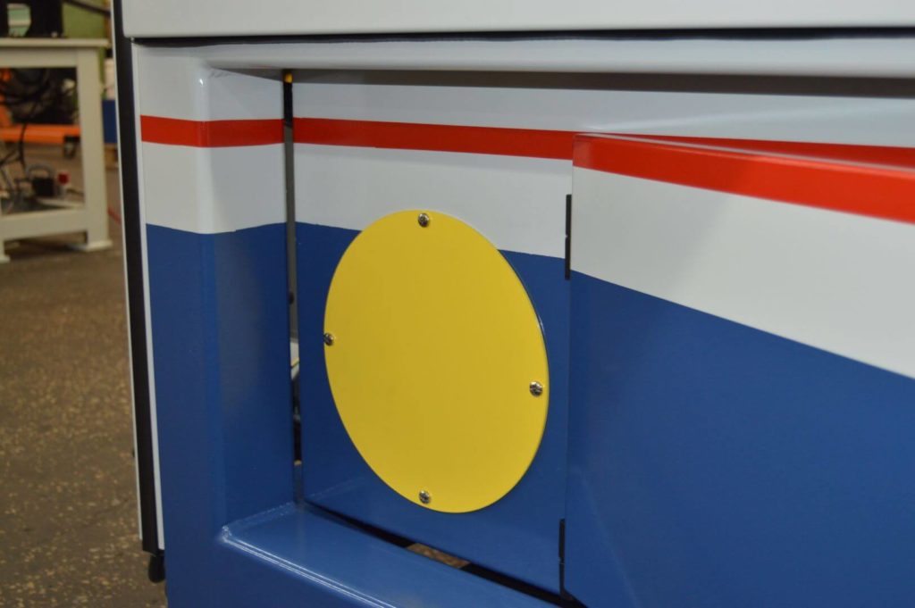
- A sheet metal enclosure is surrounded by a steel tubed frame. The machine is tall to accommodate for various shaft lengths but has a small footprint. Hanging assemblies are supported by a ¾” steel plate. Lower access panels are provided for machine floor clean up and dust collector adaptation. Pneumatic/electric panels and all robot components are mounted directly to the machine base.
Processing
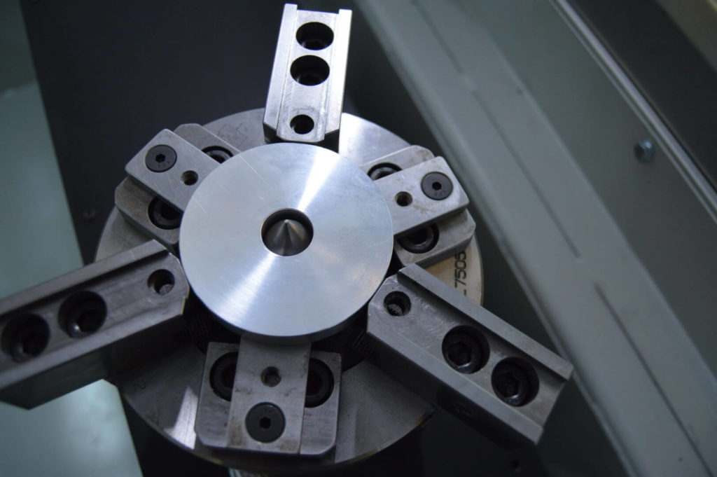
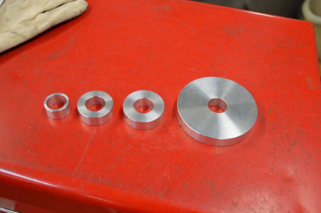
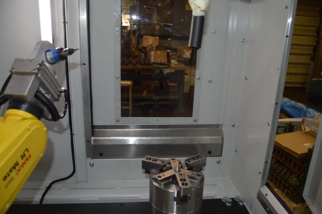
- Parts are placed on the work spindle by an operator. The work spindle consists of a KITAGAWA pneumatic chuck assembly that is belt driven by a servo/gear box. The servo drive provides excellent accuracy/repeatability. Clamp tooling is custom made per application.
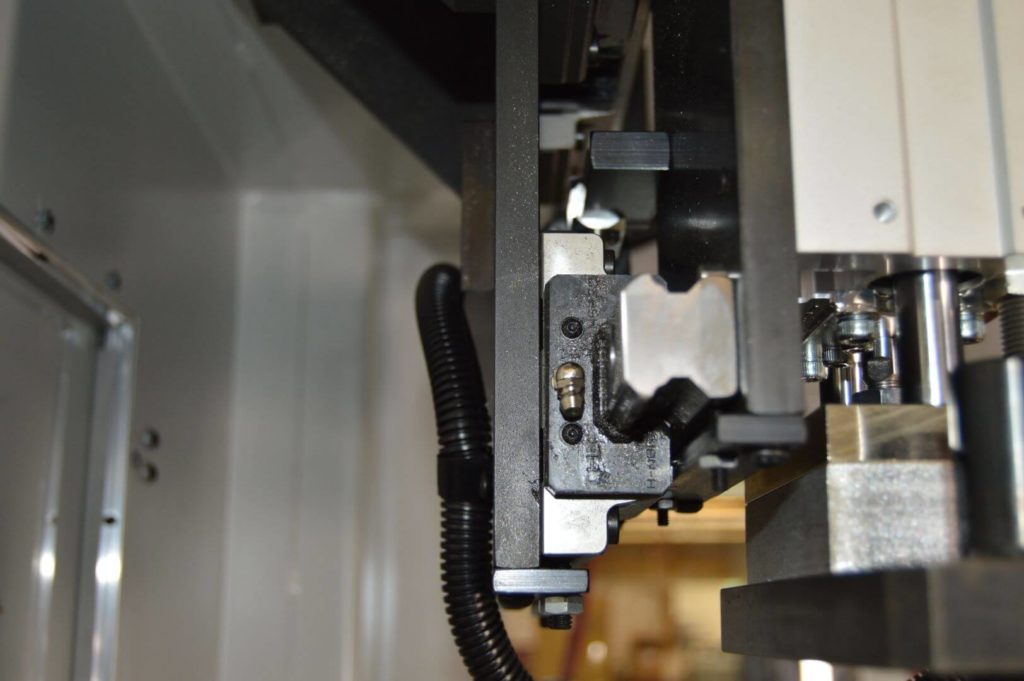
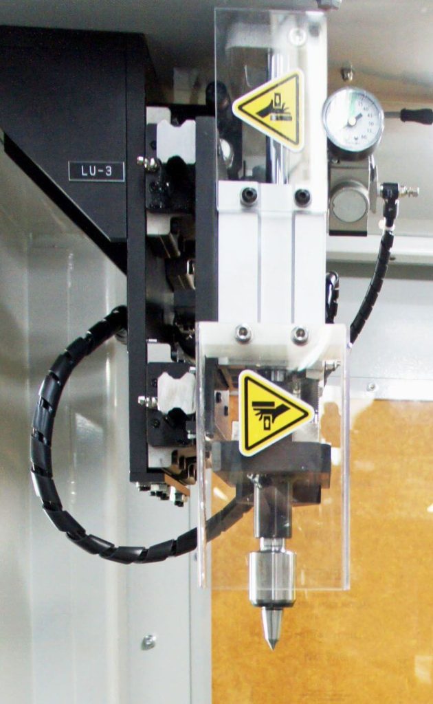
- If the part is a long shaft, a live centered tail stock assembly will engage the shaft end via pneumatic linear slide. This assembly is carried on a THK linear rail system and will retract when not needed.
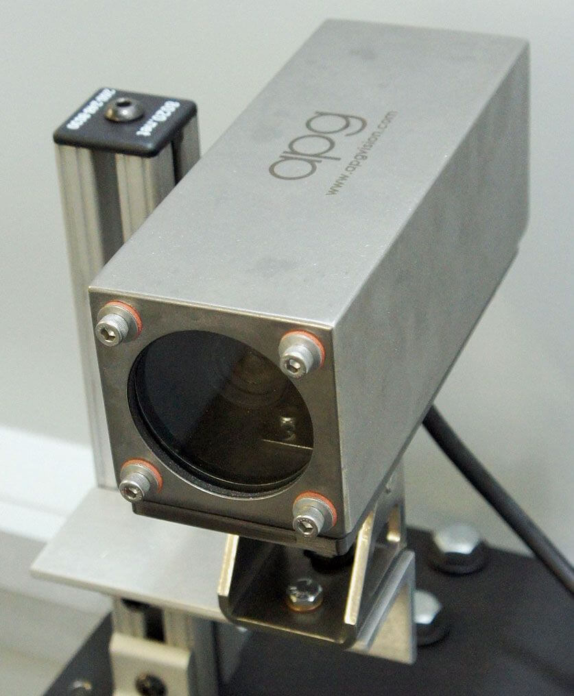
- An optional camera system identifies the part to be processed and will send an alarm if that part does not match the program that has been called.
- Once identified, the robot will move to a search position and use a laser to detect the work surface. With one quick rotation of the part spindle, the robot identifies the area to be cut.
- With a radial brush, grinding wheel or carbide rotary file, the robot moves to positions taught by the operator and performs a series of cuts. When the program commands are finished, the robot returns to its home position.
- Cutting tools are driven by high rpm air motors held near center by a pneumatic rotary actuator, allowing them to follow the work surface smoothly/freely. Rotary actuators are precision regulated to allow “cut” and “lift” pressures to be fine tuned for more/less aggressive cuts. These pressure settings can be kept/recorded to maintain cycle to cycle performance as a cutting tool wears down.
Safety/On Site Requirements
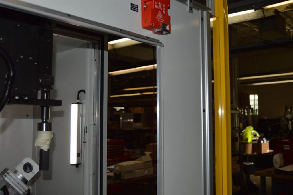
- All doors and removeable panels are either electronically interlocked or tool removeable. Physically locking door safety switches are available as an upgrade option.
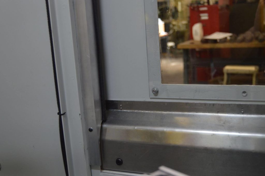
- Horizontally sliding load doors are available in automatic and manual functions. Auto doors are pneumatically driven and include the option for safety light curtains.
- Aluminum extrusion safety fencing is placed on the machine’s roof to keep operators safe from auto door functions.
- CDMC is willing to fulfill custom paint requirements for a charge.
