Large Bevel Gear Deburring
Application
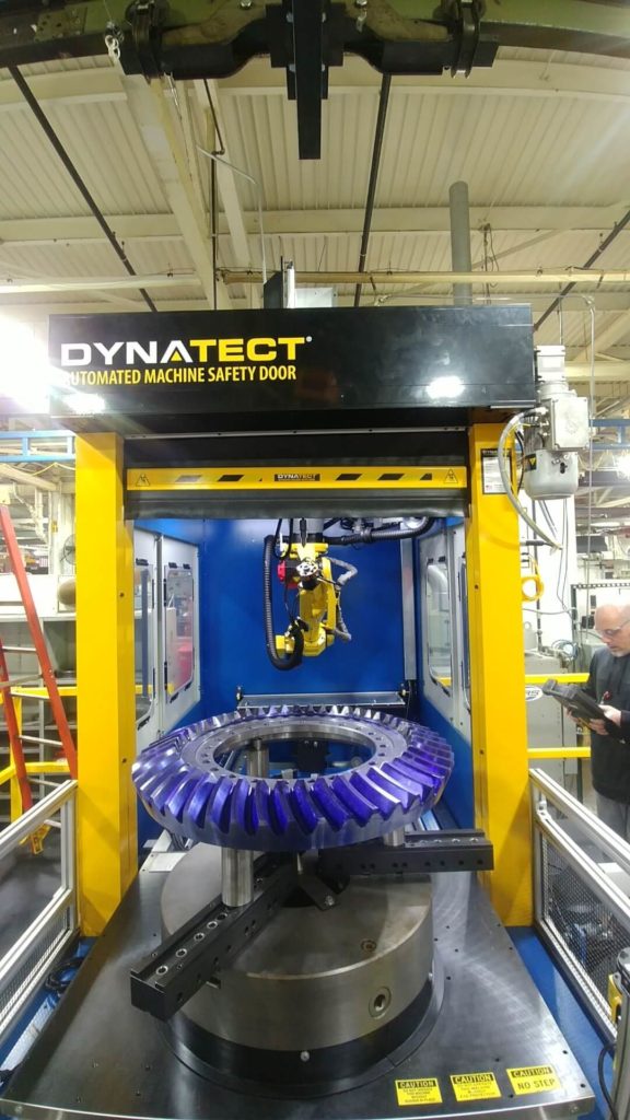
A manufacturer of various large gears needed a large bevel gear deburring system to chamfer a wide range of gears. The size/weight of some gears required the ability to gantry load the machine and a robust part drive spindle. Unique solutions were needed for an auto/safety door assembly, due to the height required to house some of the customer’s applications.
Chamfer specifications dictated the need for more accurate tool placement than could be provided by a grinder arm. The wide range of gears to be chamfered required the ability to change cutting tools on the fly. This customer required a motion sensor system at machine load to keep operators safe.
Solution
Machine Base
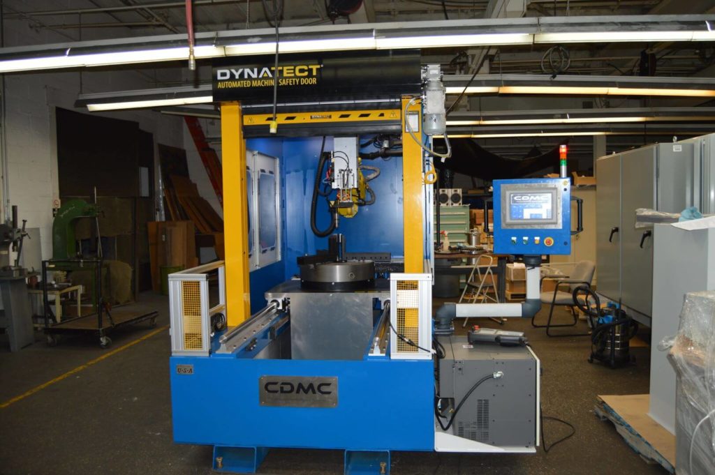
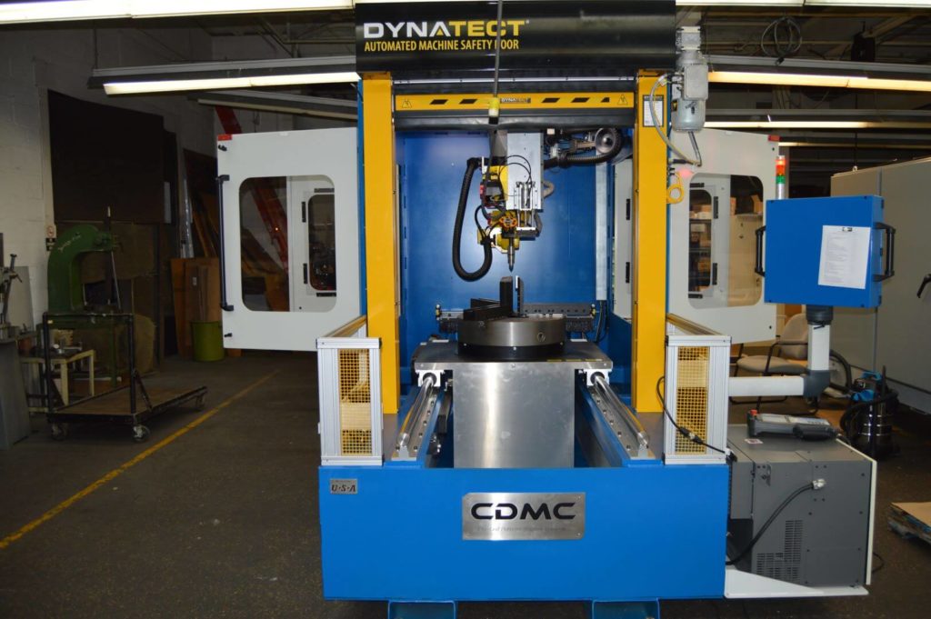
An “L” profile base made of ½” steel plate is used. A high work area is required to house the robot and accommodate a tail stock for long shafts. A lower profile front loading area and large front opening allows for loading/shuttling of very large gears.
Processing
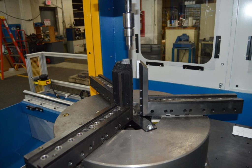
- Gears are loaded onto a large manual BISON chuck equipped with custom clamp tooling. The chuck is supported by a 1” ground steel carriage plate. Once loaded, a rack-and-pinion driven linear rail system shuttles the spindle assembly to the work position. A ring gear located beneath the chuck is driven by a D.C. motor and gearbox. Part drive speeds are adjustable via the HMI screen.
- If a long shaft has been loaded and selected with the HMI, a tail stock assembly will lower into place above the work piece and clamp the shaft end with a live center. A pneumatic linear actuator brings the center to its work position while a rack and pinion is used to move the entire assembly vertically, allowing for various shaft lengths to be processed.
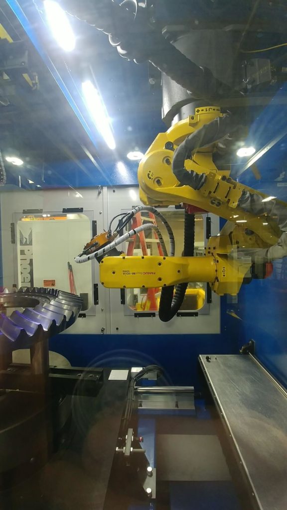
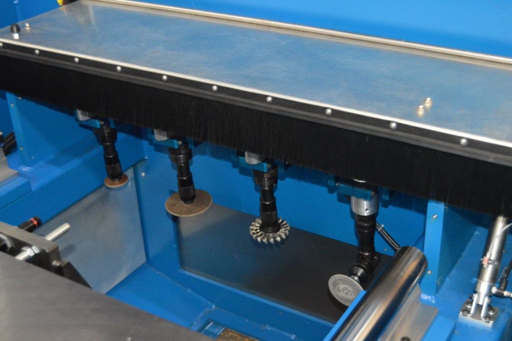
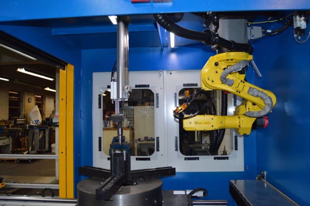
- The robot selects one of five available cutting heads from a covered tool crib located in the back corner of the work area via an ATI pneumatic tool changer. Cutting heads consist of various grinding wheels and carbide rotary files driven by air motors. Air motor speed varies depending on the cutting tool to be used. A clamping pivot holds each air motor near center and is held in the cut position by a short stroke cylinder. “Cut” and “Lift” directions are precision regulated, allowing changes in cut aggressiveness. Once the optimal cut pressure has been determined for a specific part, it can be recorded and monitored for repeatability.
- Now equipped with a cutting tool, the robot will perform a set of commands taught by one of CDMC’s FANUC robot programmers as the part spindle rotates. Many work programs can be stored within the program PLC and called upon via the HMI.
Safety Implementations
- All manual doors are electronically interlocked. Opening a manual door during a machine cycle will immediately stop the machine and send it into a fault state.
- A pair of STI safety scanners are placed at each front corner of the machine. These sensors detect bodies that are too near the load area and will disallow cycle start up if the safe area is breached. Any machine area not seen by these sensors is protected by an extrusion/mesh fence.
- A DYNATECT roll out auto door is used at the front opening of the machine. This solution allows there to be a large opening without the need for a large heavy door panel.