Saw-Blank Deburring
Case Study A
JOB NO. 249
THROUGH-FEED BAND SAW BLADE DEBURRING
Application
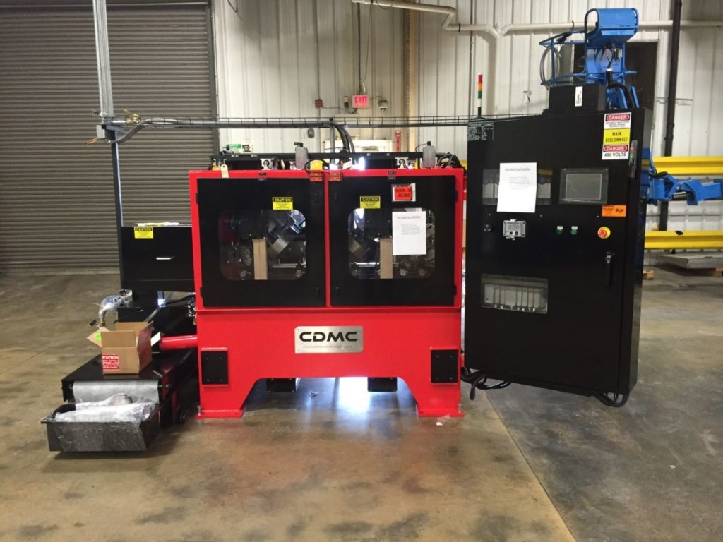
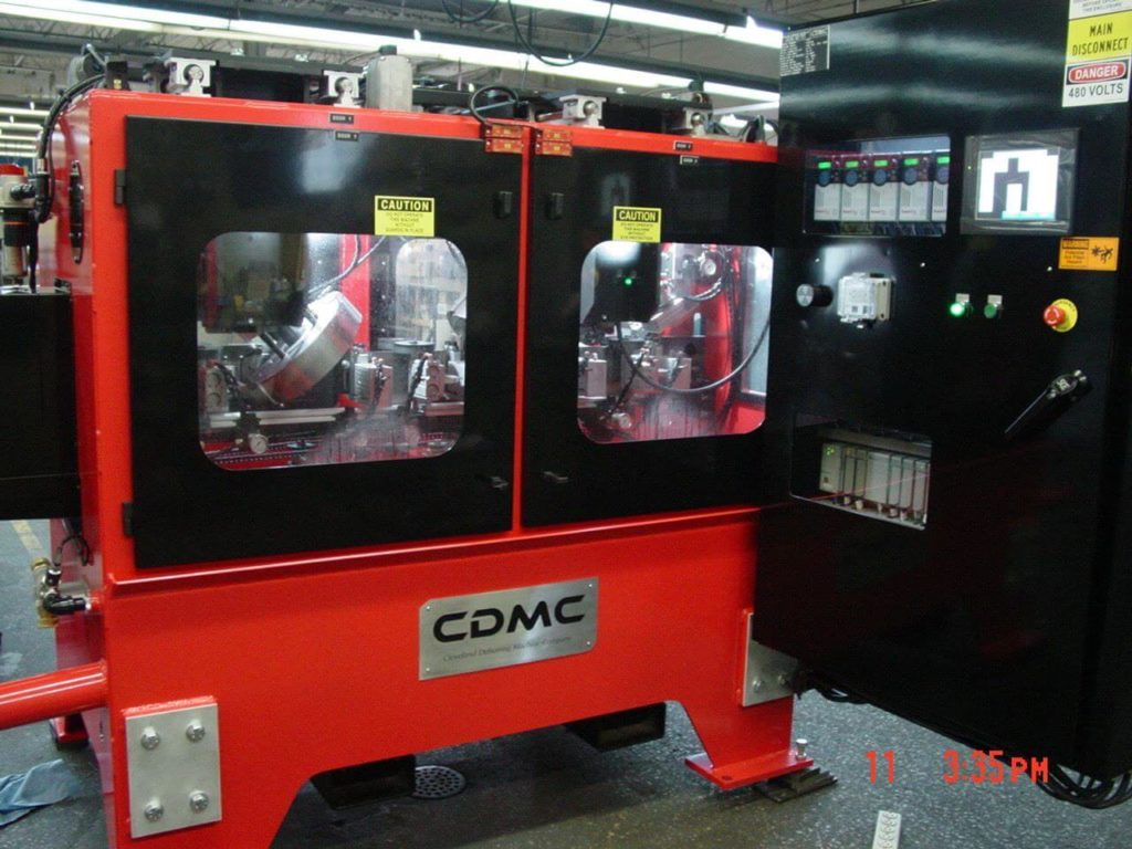
A top manufacturer of cutting and construction tools needed a way to deburr large band saw blade coils prior to shipment. Coils were long and heavy, needing to be fed from a customer-owned coiling machine, through CDMC deburring equipment and back to another coiling machine. Blade entry/exit points near any operator activity needed to be well guarded.
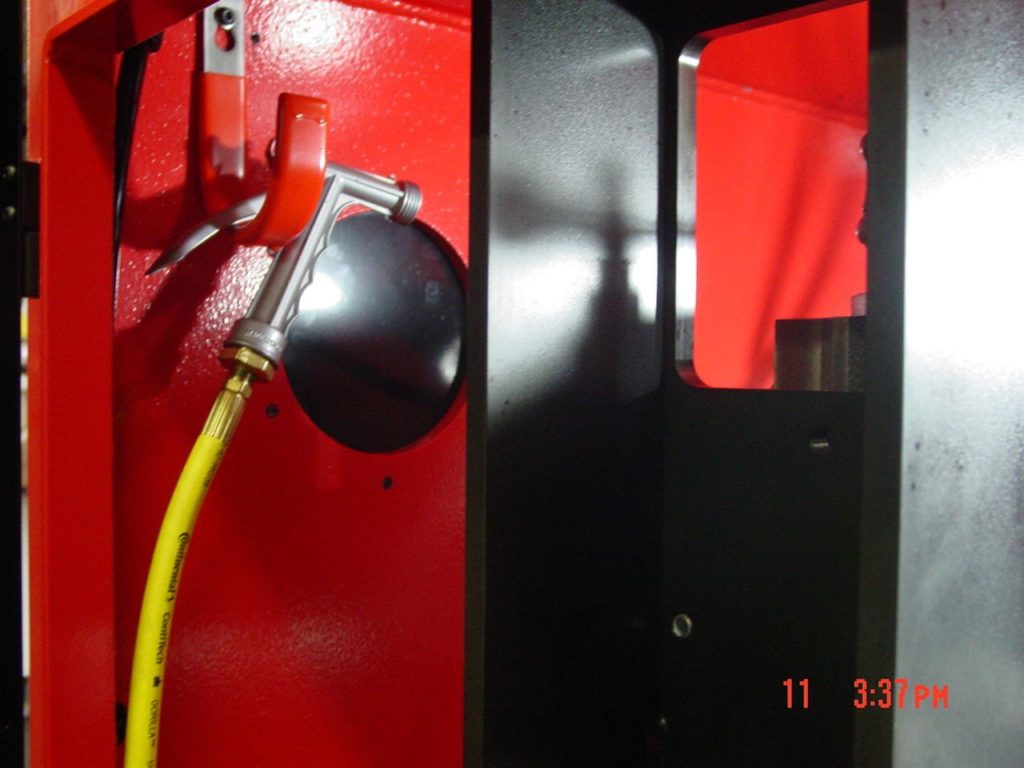
To protect the machine surfaces from debris build up and help to aid burr removal, a wet machine was specified. The coolant system would need integrated cleaning systems to prevent coolant breakdown.
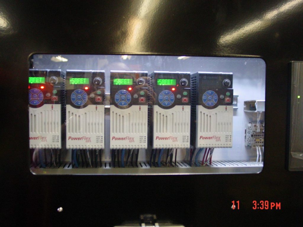
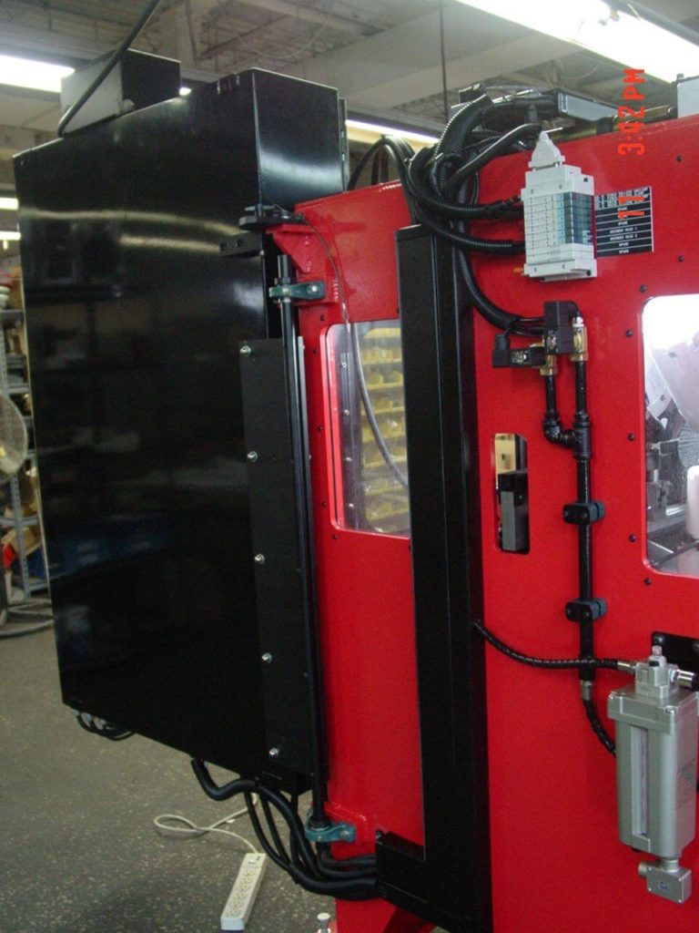
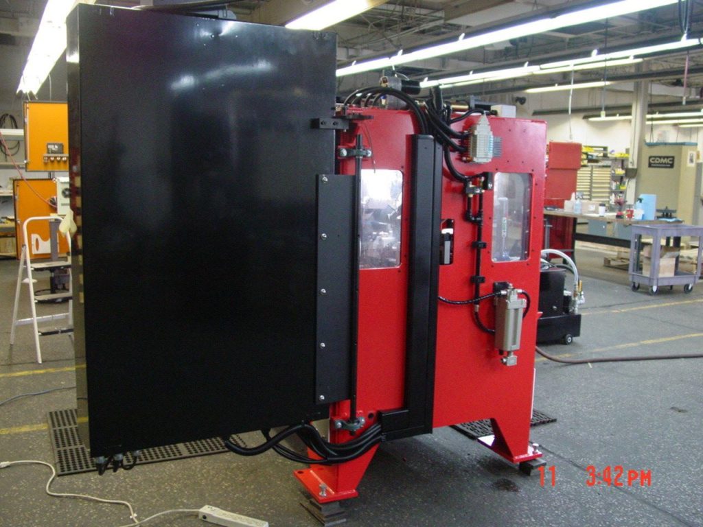
The customer requested a pivoting electrical cabinet with custom doors and a custom paint job.
Solution
Processing
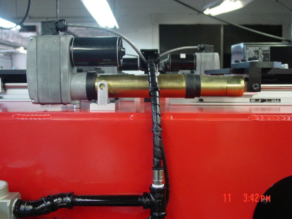
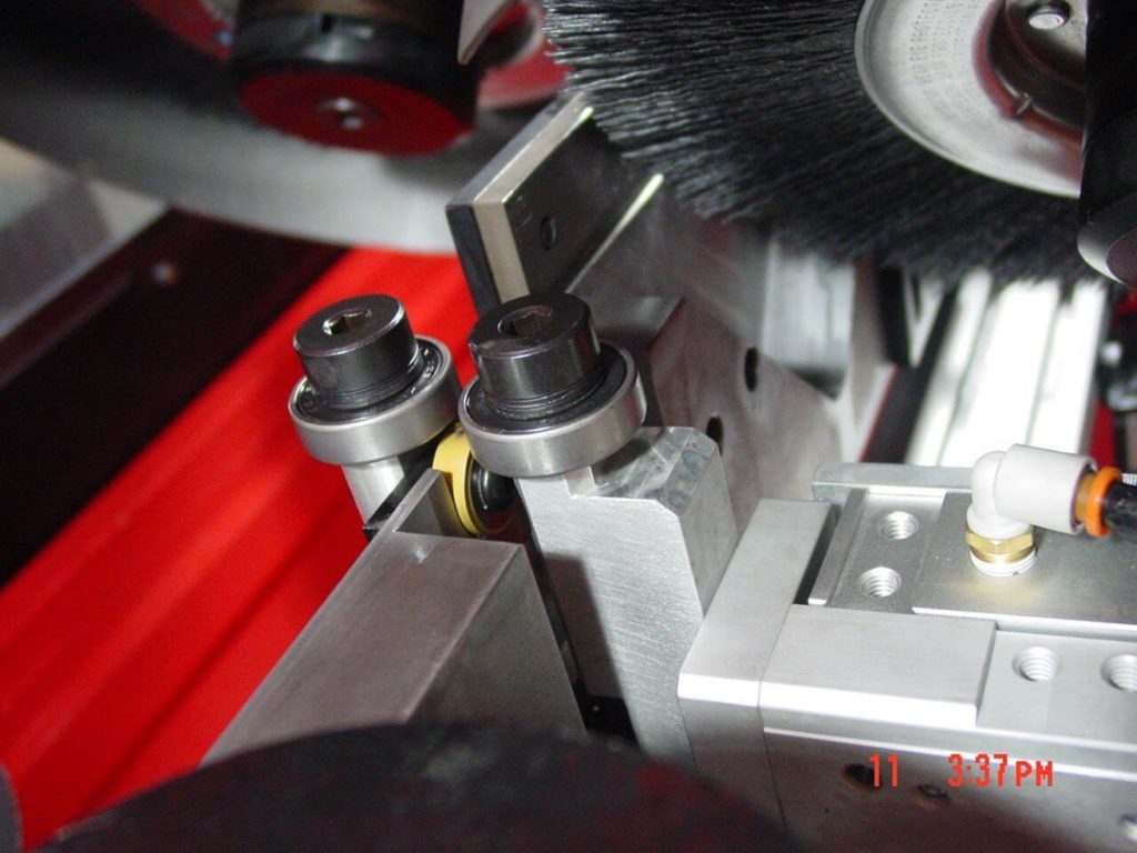
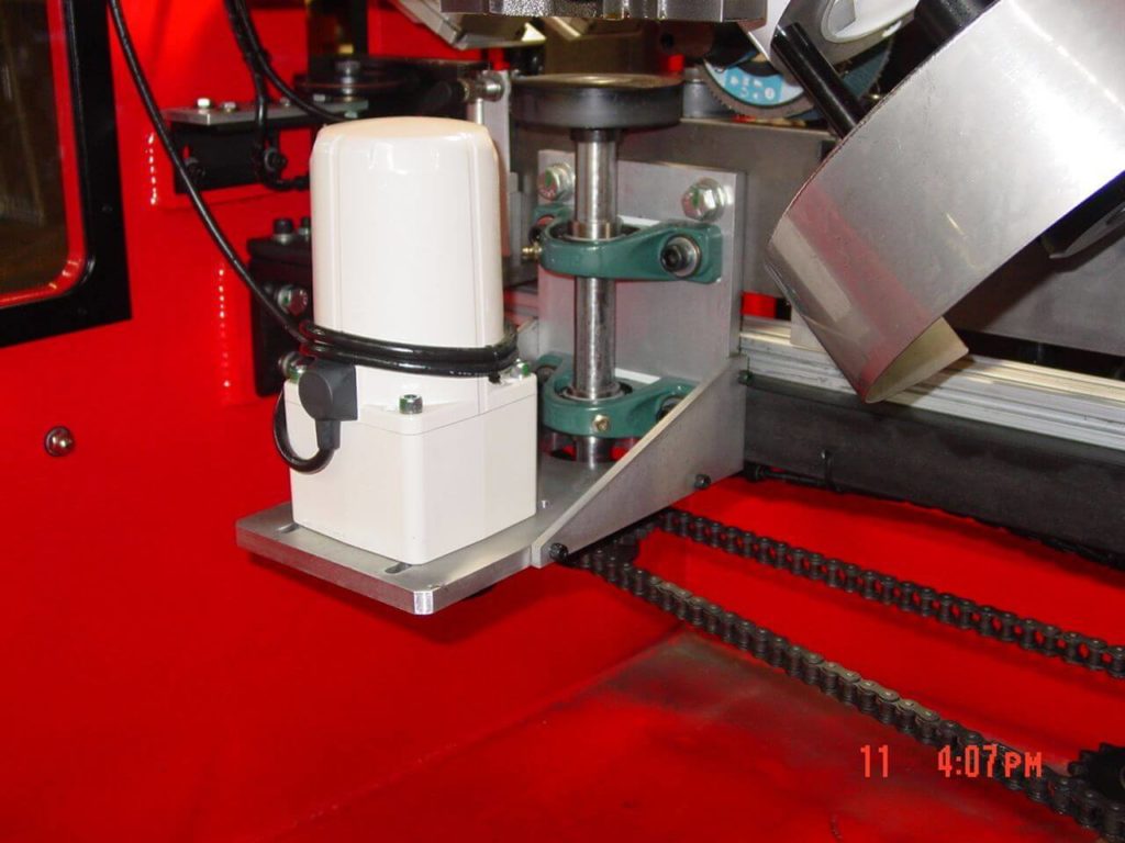
- The machine is fitted with a drive roller/idler system in order to feed long lengths of blade from/to the entry/exit coilers. Rubber drive rollers and steel/carbide idler rollers mounted to linear pneumatic slides use air pressure to clamp and drive/guide the blade through the deburring process. The entire drive system is chain-driven by a single, high torque electric motor. Steel side guides exist wherever a roller assembly does not.
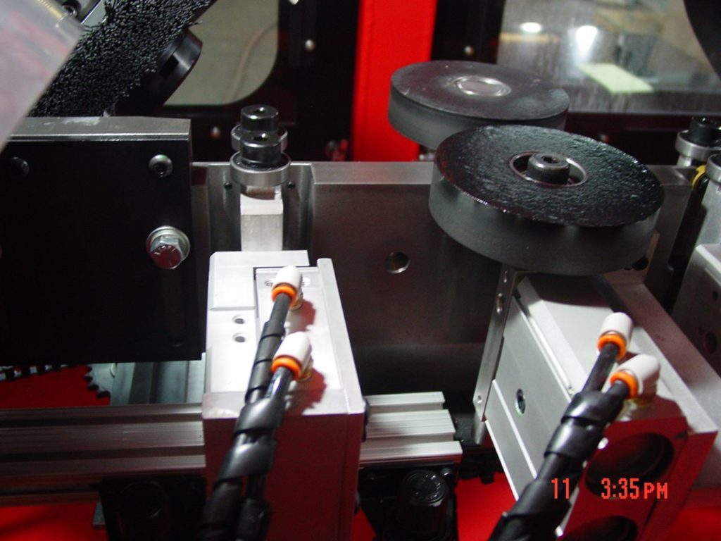
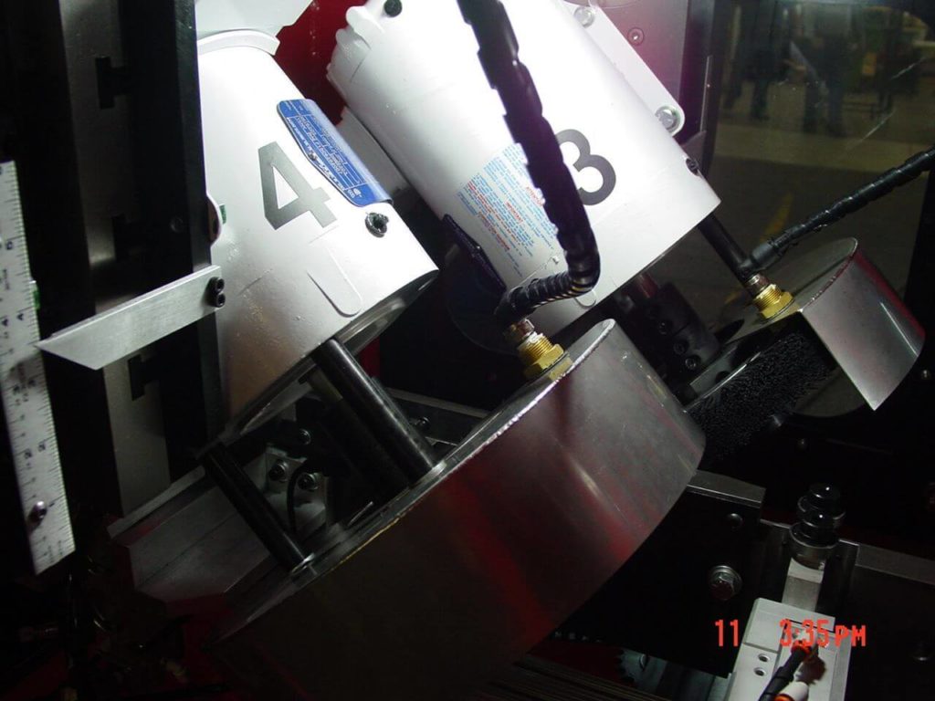
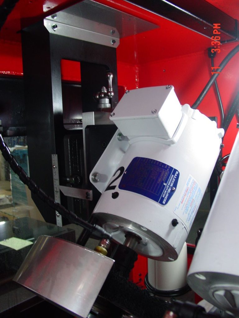
- In process, the blade passes through a set of 4 nylon abrasive radial brushes directly driven by large electric motors. The motor assemblies consist of a pivot to allow for contact angle changes, and a manual vertical adjustment with scale readout (via a manual Palmgren slide). Radial brushes are 10”-14” in diameter.
- Brush motor assemblies are carried by linear rail/carriage assemblies located on the exterior roof of the machine. This motion is controlled by an intelligent linear actuator that takes amperage feedback from the brush motors to determine feed and retract distances (Auto Amp Compensation). Once the optimal feedback percentages have been determined by the operator, these parameters can be saved to keep deburr quality consistent.
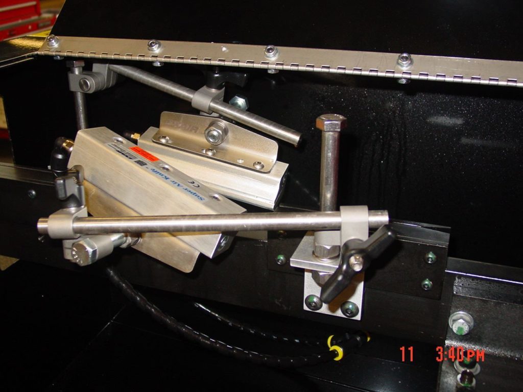
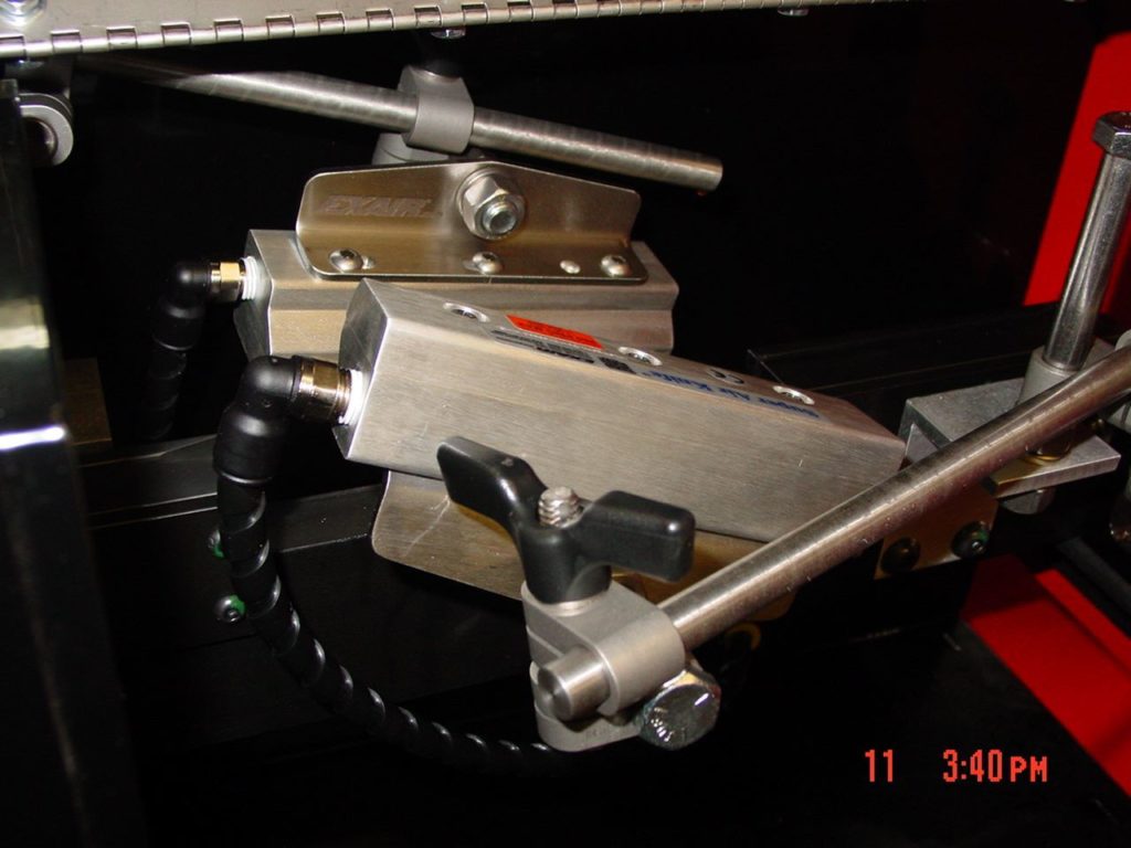
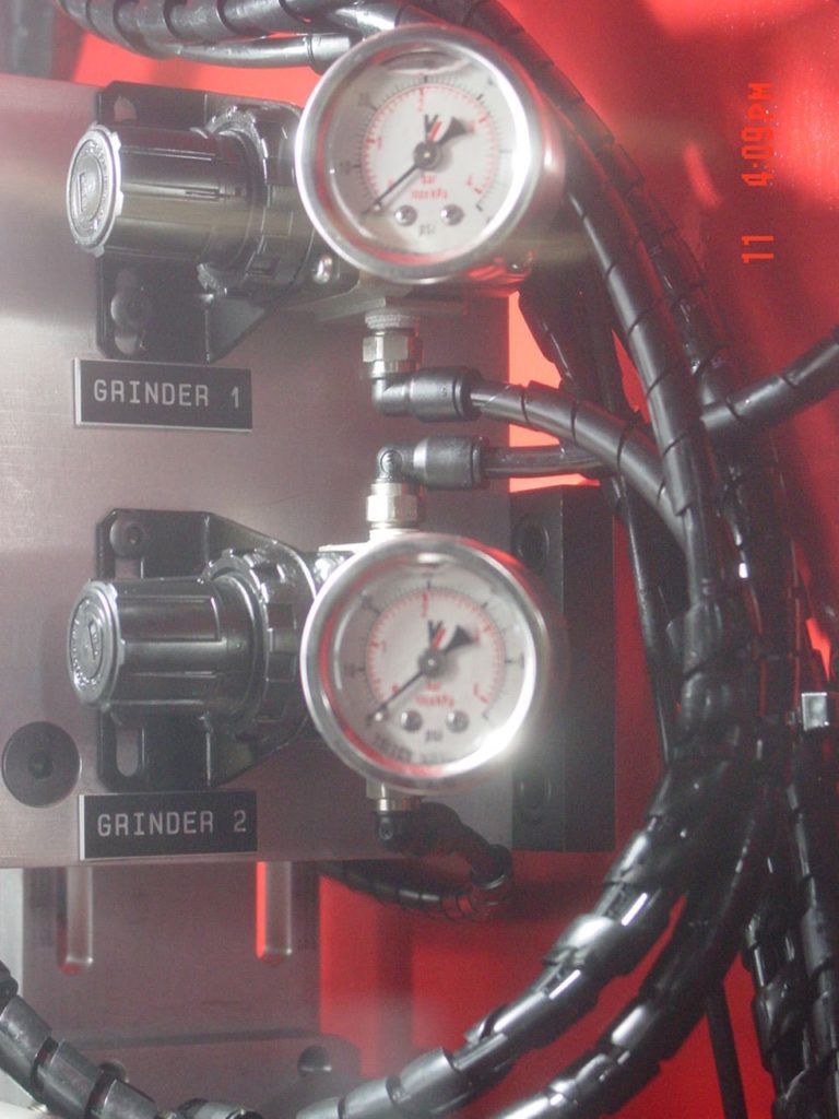
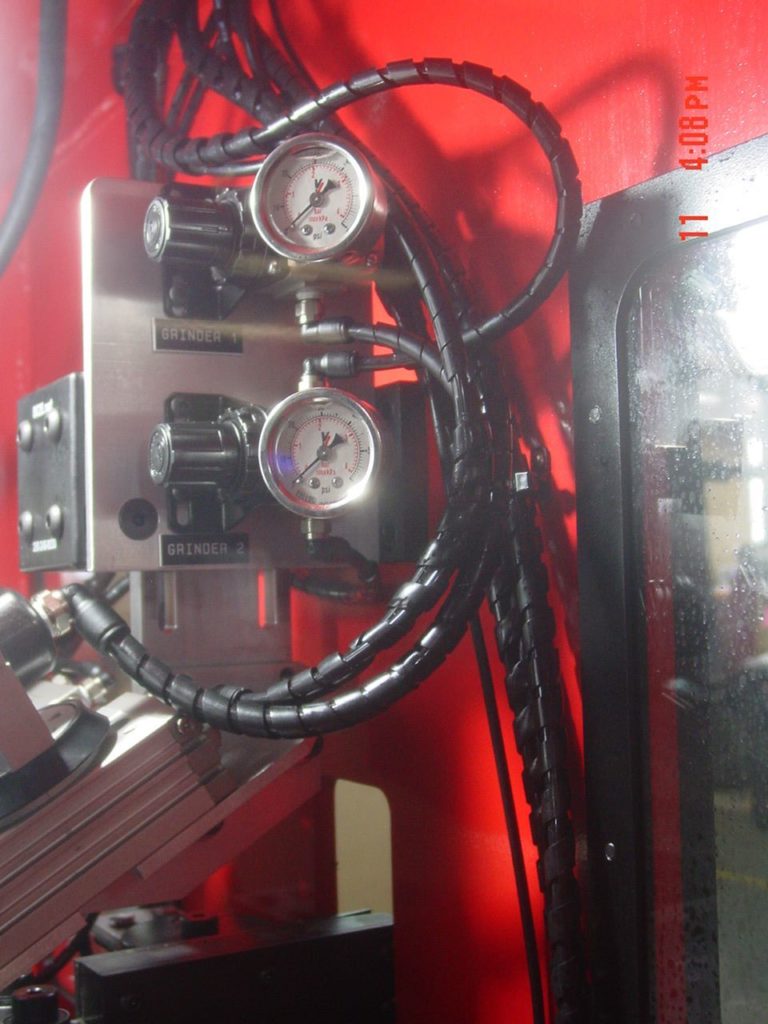
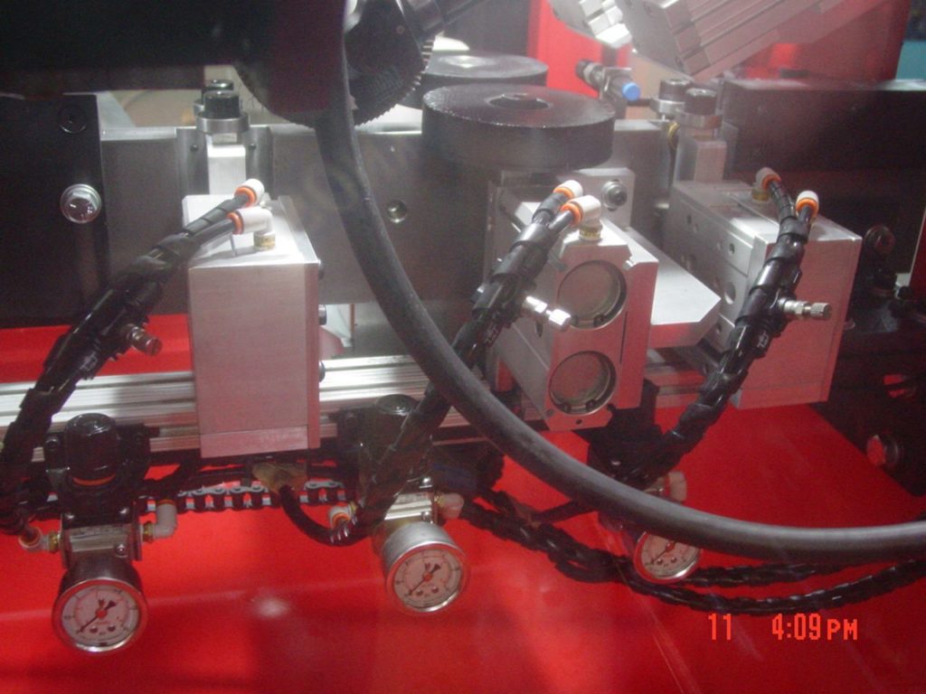
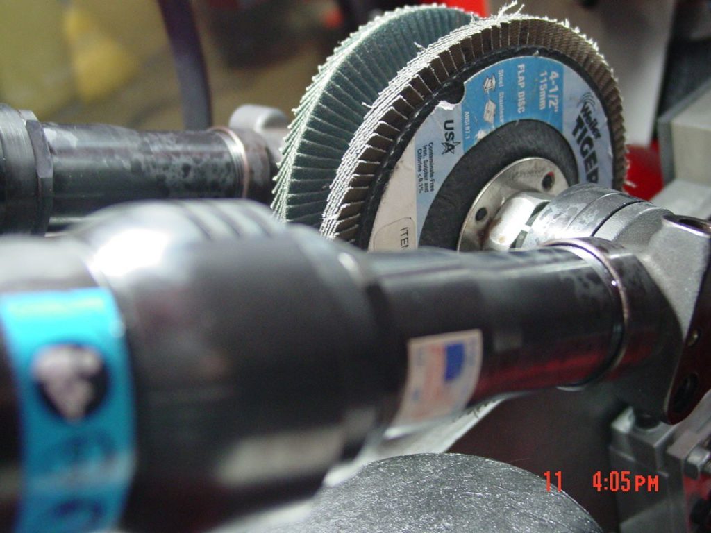
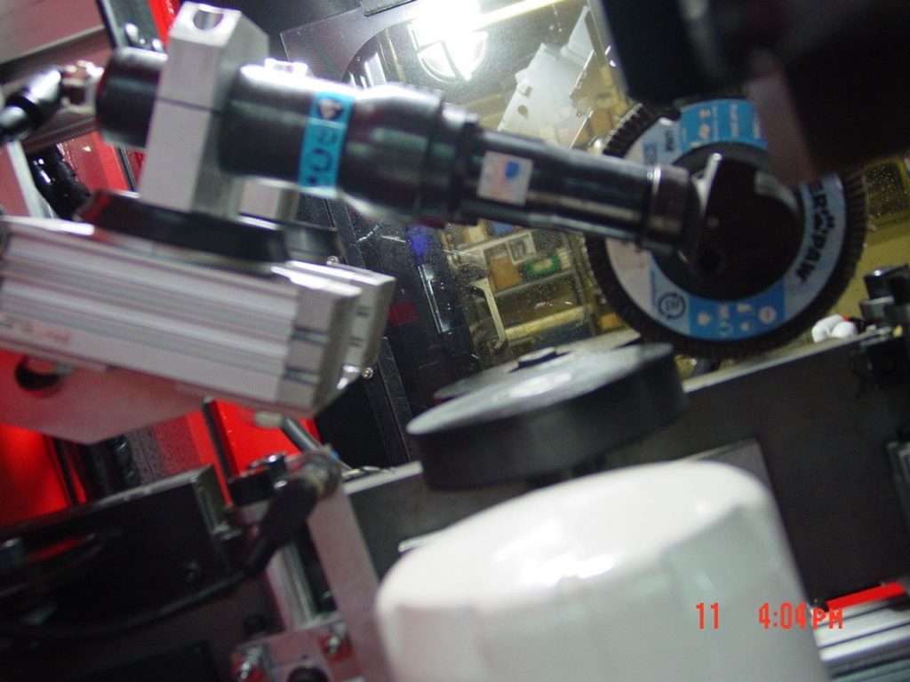
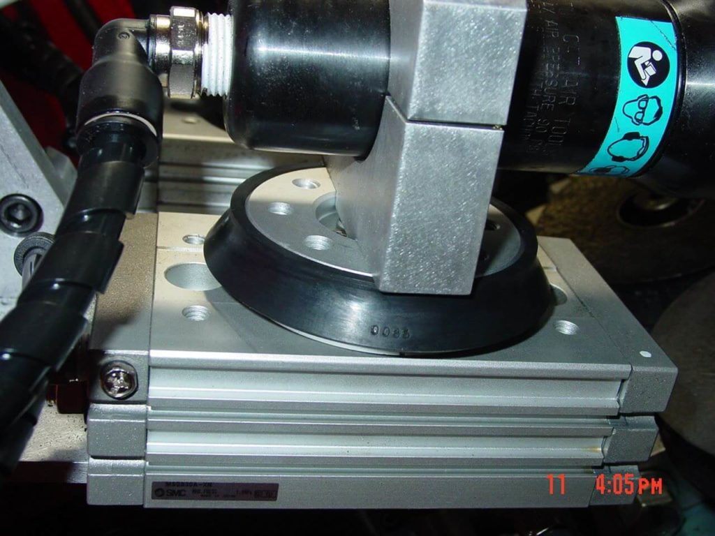
- For more difficult burrs, the blade passes through a pair of mirrored abrasive flap discs driven by air motors. The air motors are held near center by a pair of pneumatic rotary actuators. Cut and lift pressures to these rotaries are monitored and adjusted via precision regulators.
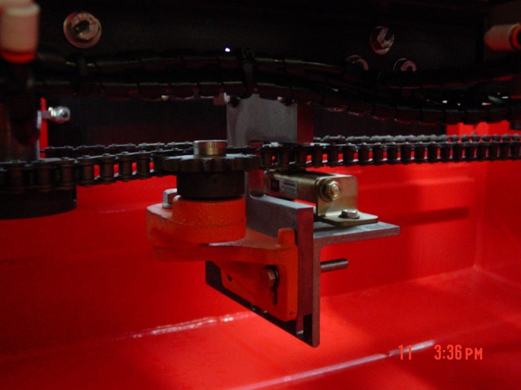
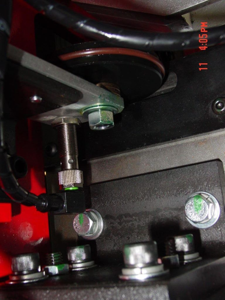
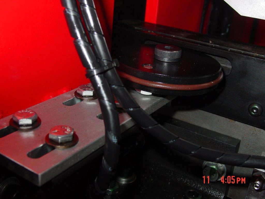
- Just before exiting the deburring machine, the blade passes through an encoder assembly consisting of a rubberized wheel and target/counter. If this counter fails to read a revolution, the machine will enter an idle/fault state.
- Hinged, sheet metal cover(s) keeps exit and entry points safe from human interaction.
Coolant System
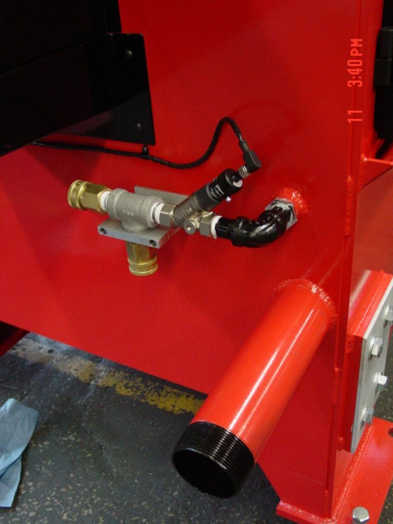
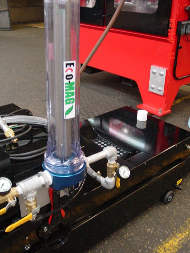
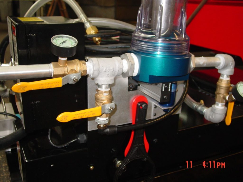
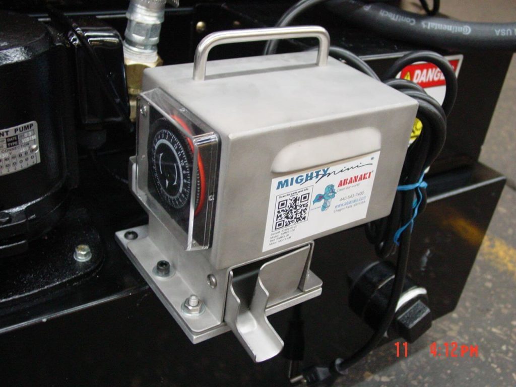
- A purchased high-flow coolant tank is used to feed coolant to cut points within the machine. This tank is enhanced with a magnetic separator (to remove particles from recirculation) and an oil skimmer to extend coolant life. All coolant plumbing is done in-house.
Customization
- The base has been sent out to one of our painting contractors per the customer’s paint spec. CDMC is willing to comply with most specs for a cost.
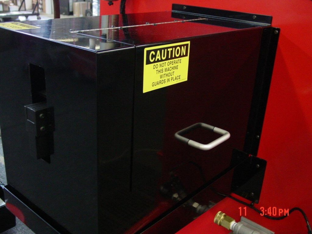
- Windows are added to electrical cabinet doors to allow systems monitoring by operators and management without the need to expose internal electronics. This is done via water jet prior to build commencement.
- A pivoting electrical cabinet allows monitoring from different angles within the machine cell area. The cabinet can be secured via a plate and pin system located near the top of the pivot assembly.