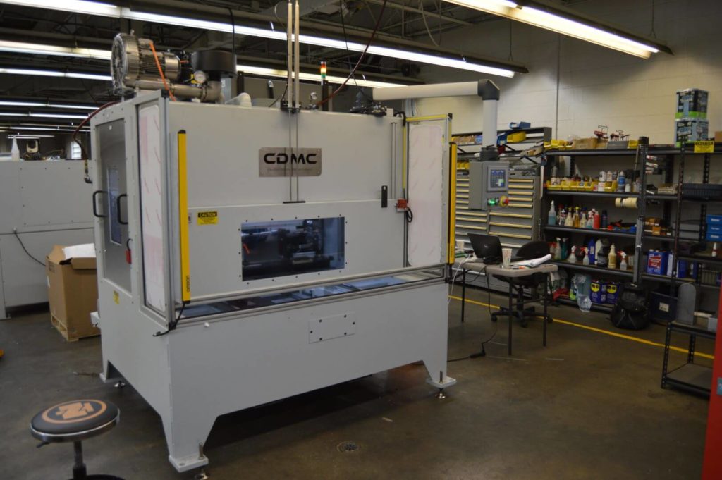
Screw Compressor Rotor Deburring and Finishing
JOB NO. 307
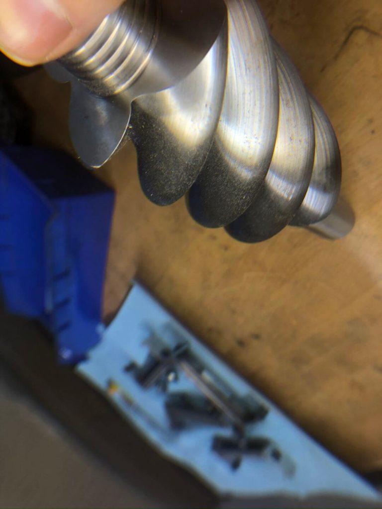
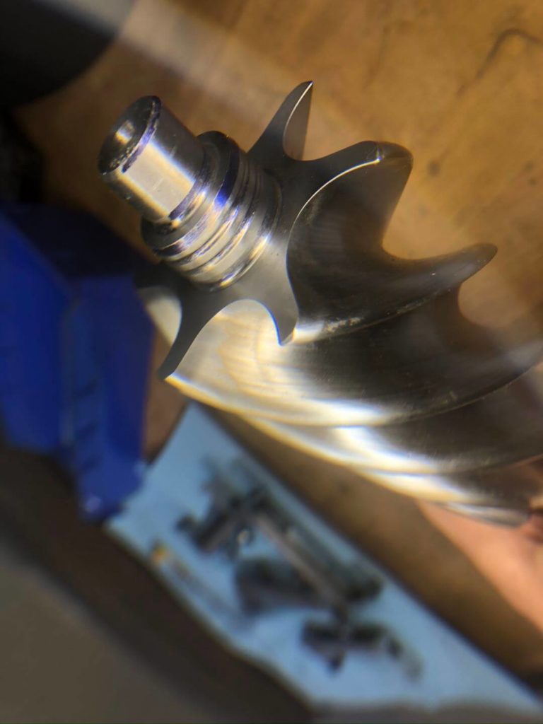
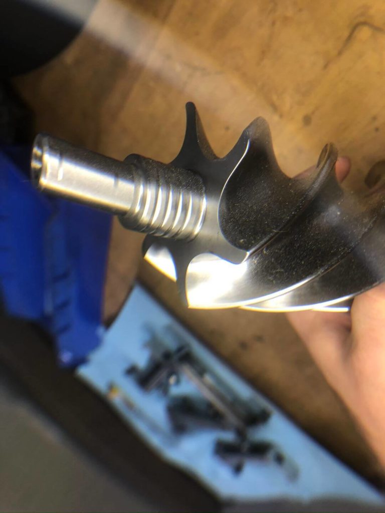
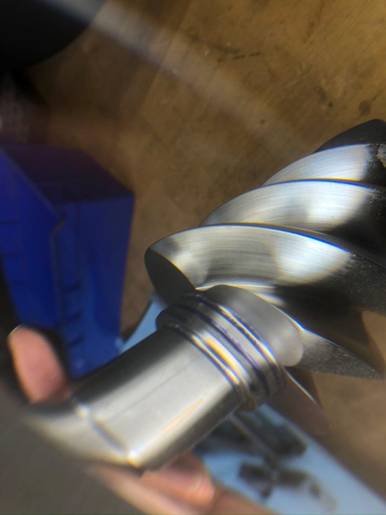
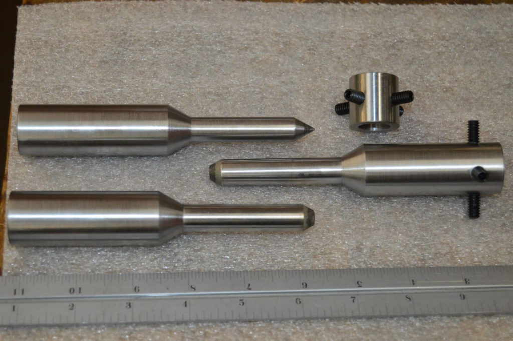
COMPRESSOR SHAFT DEBURRING
Application
A leading manufacturer of air compressors needed a deburring and finishing solution to edge break sharp surfaces on a family of shafts. The machine needed to accommodate for a fairly large range of part lengths and process all parts within a short cycle time. A shuttling part drive would be required for safe/easy loading. A wet process would be required to aid in the brushing process and machine cleanliness along with a blow-off system to dry parts before unload.
Solution
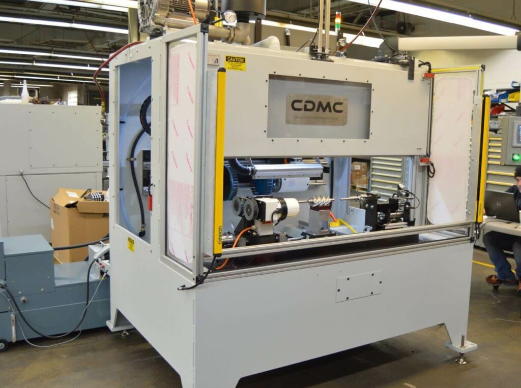
Machine Base
- A wide profile 1/2” steel wall base is used in order to support a heavy-duty shuttle and brush head assemblies. The base is deeper at the bottom to allow for a shuttling part drive assembly.
- The base is welded water-tight to prevent coolant leakage.
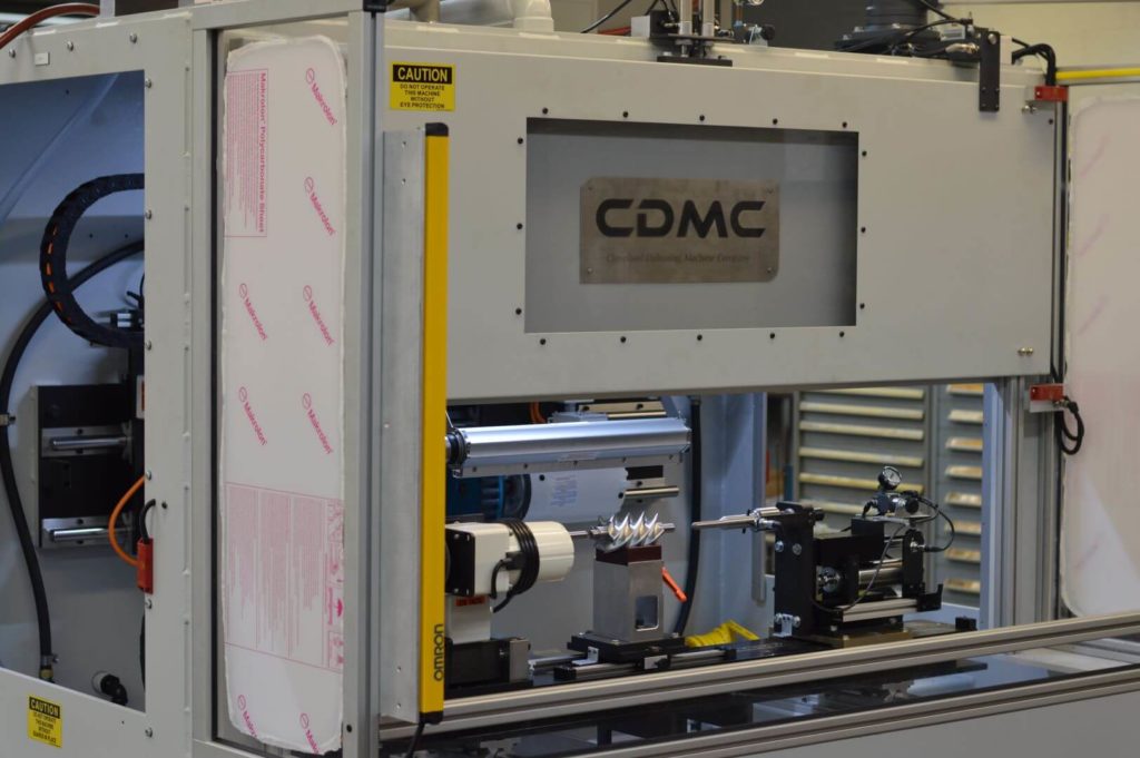
Processing
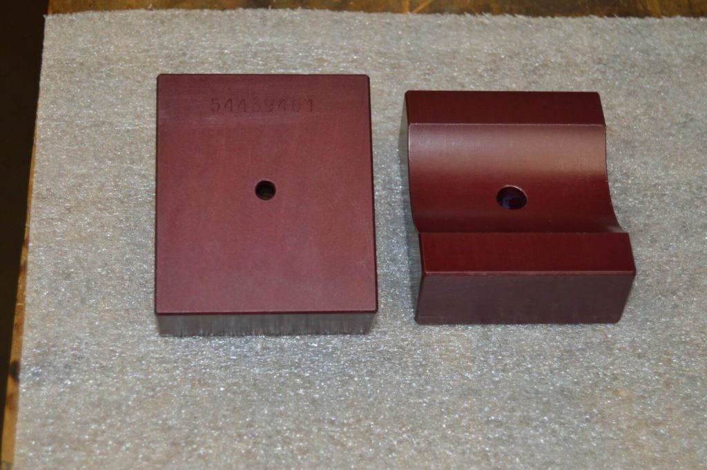
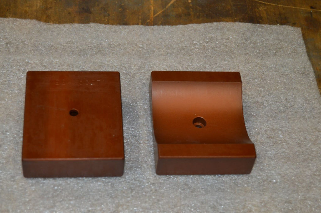
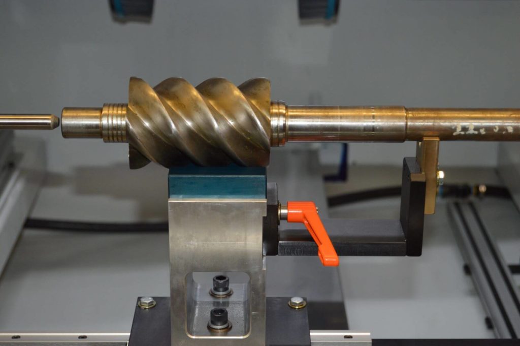
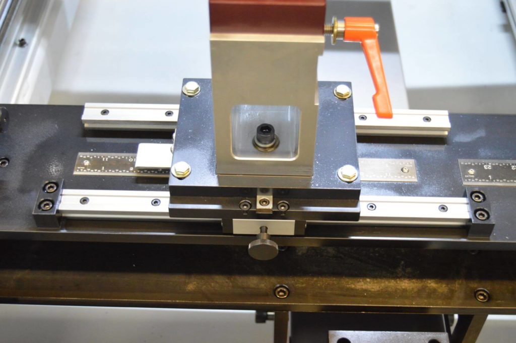
- Shafts are loaded by hand or via robot onto custom rest tooling. This quick-change tooling is made of anodized aluminum and will hold the part in the correct orientation to be clamped. All rest/clamp assemblies are adjustable along a ½” steel rail plate to accommodate for various work pieces.
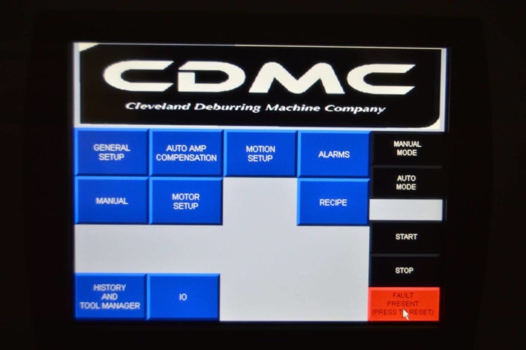
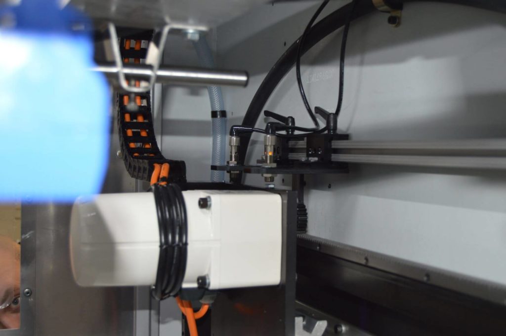
- An electronic linear actuator brings the rail/part drive plate into working position as a cycle is initiated via HMI. This intelligent actuator provides positional feedback to the program PLC and determines feed depth from part to part.
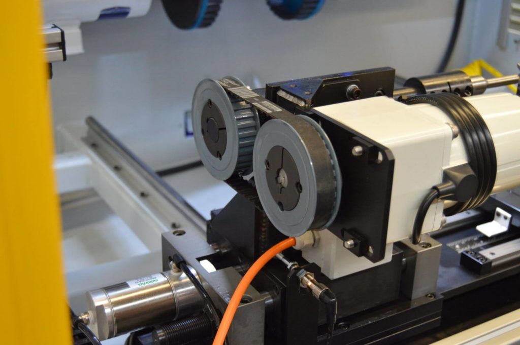
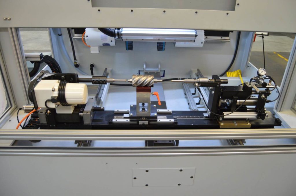
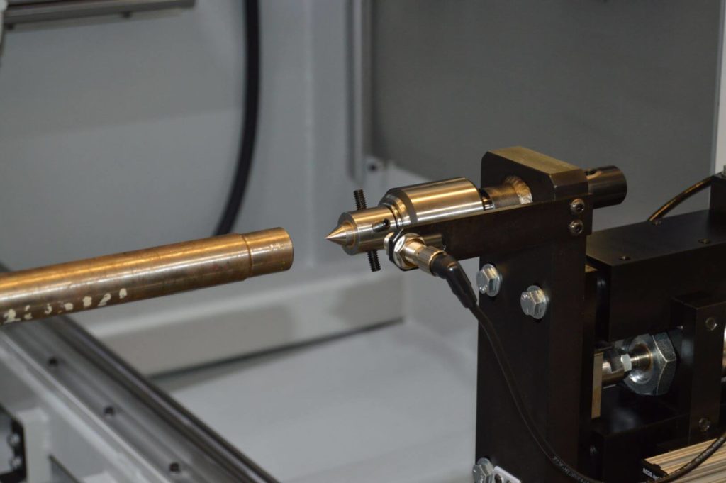
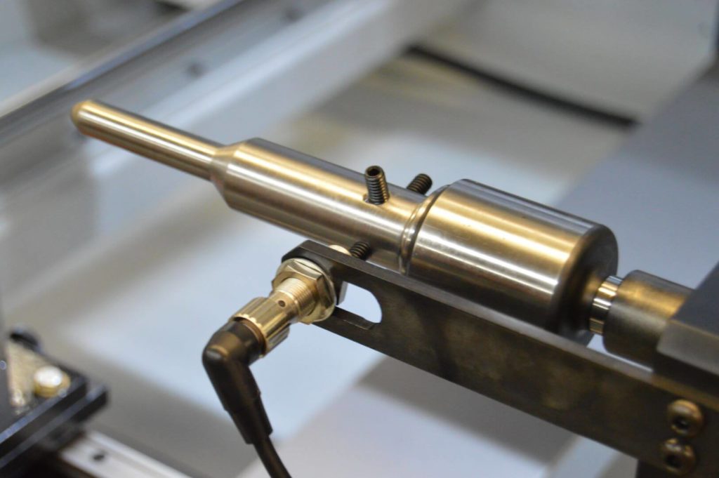
- The work piece is clamped in place, much like a lathe, by an offset belt-driven head stock assembly and a pneumatic linear slide driven tail stock assembly. All clamp tooling is custom made by CDMC and spray-welded for extra grip. The head/tailstock pick the work piece up slightly from the rest tooling and begin to rotate.
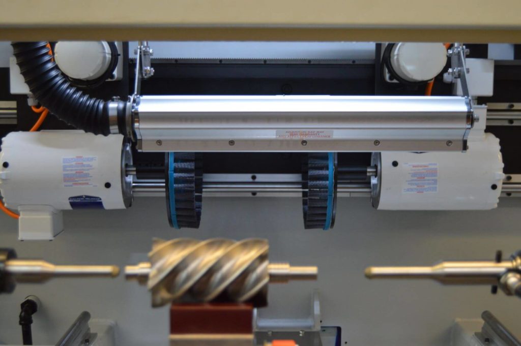
- Two directly driven nylon abrasive end brushes travel to the work position and brush the work surface using cut forces determined by Auto Amp Compensation settings. Brush motors are mounted to a rack and pin assembly driven by a high-torque A/C motor.
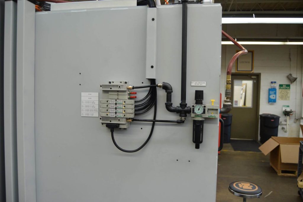
- Nozzles positioned above the work area provide a steady flow of coolant to aid in cutting.
- As the work cycle finishes, a large air knife pressurizes via independent blower motor located on the machine’s roof. The air knife dries the work piece as it is rotated by the head stock.
Safety Implementations
- Dual cylinder auto door assembly keeps operators safe during cycle initiation. A pneumatically driven safety pin holds the auto door in place if maintenance personnel need to be in the work area. Safety light curtains are mounted to aluminum extrusion safety fencing at either end of the load area.
- All manual doors are electronically interlocked. If interlocks are broken mid-cycle, the machine will stop and enter a fault state.
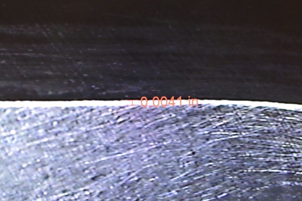
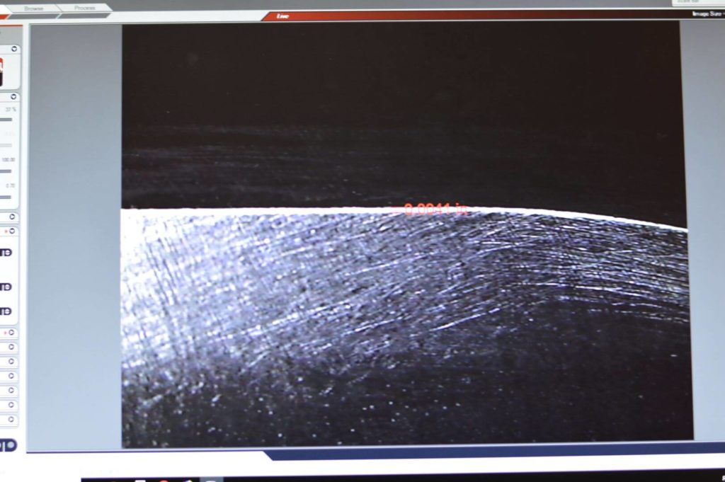
Results